
 Contact Us
Introduction to Large Deflection/Deformation in Ansys Mechanical
Structural stiffness depends on more than material properties. As a component deforms, rotates, or develops stress, its geometry and stiffness can change significantly, affecting the accuracy of simulation results.
Large deflection in Ansys Mechanical accounts for these geometric nonlinearities, providing a more realistic representation of structural behavior when small-deformation assumptions are no longer sufficient.
In this article, we’ll explore four effects associated with large deflection analysis—large strain, large rotation, stress stiffening, and spin softening—and examine practical examples that demonstrate their influence on simulation results.
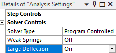
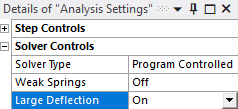
In Ansys Mechanical, select Analysis Settings, expand Solver Controls, and set Large Deflection to On.
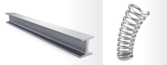
This formulation is used when the shape of the system changes significantly and/or stress develops in the part. The stiffness of a system depends on both the material and the geometry of the system. For instance, a bar of steel has a very stiff response compared to a spring made of the same material. So, it is important to take the shape of the system into consideration when calculating its overall stiffness. A large deformation formulation introduces different types of geometric nonlinearities.
Four Types of Geometry Nonlinearities
Geometric nonlinearities refer to the nonlinearities in the structure or component due to the changing geometry as it deflects. That is, the stiffness [K] is a function of the displacements {u}. The stiffness changes because the shape changes and/or the material rotates. The large deflection setting accounts for four types of geometric nonlinearities:
- Large Strain assumes the strains are no longer infinitesimal (they are finite). Shape changes (e.g. area, thickness, etc.) are also accounted for. Deflections and rotations may be arbitrarily large. (e.g. a fishing pole under tension)
- Large Rotation assumes that the rotations are large, but the mechanical strains (those that cause stresses) are evaluated using linearized expressions. The structure is assumed not to change shape except for rigid body motions. The elements of this class refer to the original configuration. (e.g. rotating parts in an engine)
- Stress Stiffening assumes that both strains and rotations are small. A 1st order approximation to the rotations is used to capture some nonlinear rotation effects. (e.g. tuning a guitar string)
- Spin Softening also assumes that both strains and rotations are small. This option accounts for the coupling between the transverse vibrational motion and the centrifugal force due to an angular velocity. (e.g. wind turbine in operation)
All elements support the spin softening capability, while only some of the elements support the other options. For more information, see the Ansys help Element Reference.
Large Strain
Fishing Rod Example
Let’s consider large deflection/deformation in Ansys Mechanical with a fishing rod as an example. It is held on one end and the weight of the fish on the other end will apply a torque which is directly proportional to the length of the rod. Since the fishing pole is long and slender it bends very easily and in that process its length changes, which in turn changes the amount of torque. If we do not consider the change in shape, then we will not account for the changing torque value and will eventually calculate the deformation incorrectly.

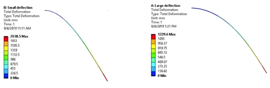
The weight of the fish causes the rod to bend significantly. Large strain nonlinearity is present, so large deflection is needed. Let’s solve this using both the small and large strain formulation to see how it impacts the solution.
M₀ = W × l₀ M₁ = W × l₁
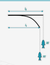
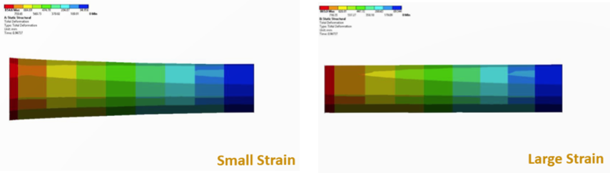
As ‘l’ decreases, M decreases and the tip deflection reduces. Also, the fishing rod gets stiffer due to stress. Small strain formulation does not account for change in shape, so the moment does not reduce as it is supposed to. So, tip deflection calculated by small strain formulation is more than that of large strain formulation.
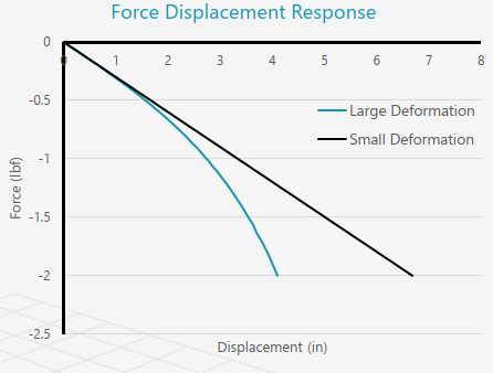
Here’s the force-displacement response from both cases. One can see that at small loads both the responses are in good agreement. Difference becomes significant at higher loads. Large strain formulation is always recommended when there are noticeable changes in the shape of the structure.
Large Strain Theory
Next in our deflection in Ansys Mechanical example, let’s look at a measure of strain called the Lagrange strain.
E = ½(FTF − I)
Physical meaning: it quantifies the change in length of a material unit. Since F is a function of displacement, we can substitute these relations:
F = I + ∂u/∂X
Below are the Large and Small Strain equations:
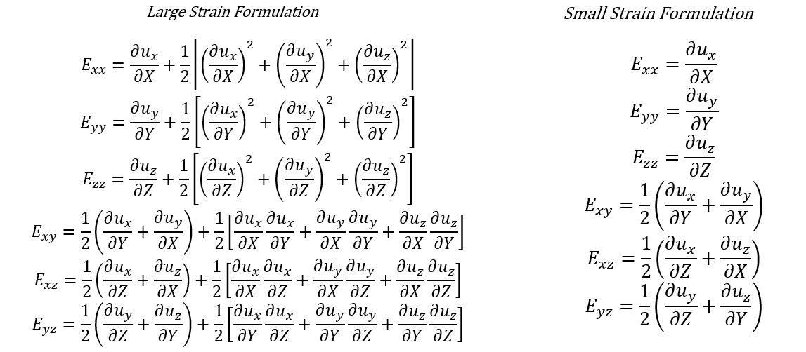
- The key difference between large and small strain formulations is the exclusion of quadratic terms in strain calculations.
- At small strains, the quadratic terms are negligible but at larger strains they are significant.
- The presence of quadratic terms in the large strain formulation makes the calculation nonlinear.
Large Rotation
Overview
Mathematically, when we approximate rotations as small rotations, we can approximate some of the nonlinear functions such as sin(θ) ≈ θ; cos(θ) ≈ 1. This approximation allows us to linearize governing equations and use a linear solver. However, at large rotation, this approximation is invalid and may result in a radial growth of the components, which is not physical. It’s important to take this into account with rotating components such as a drive shaft that are subjected to torsional loads.
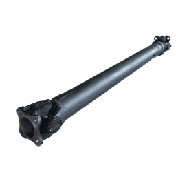
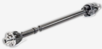
Drive shafts are used in transferring power from engines to wheels. Shafts are subjected to torque loads which creates shear stress in them. As a result, they twist about their own axis and in some cases undergo rigid rotation about their own axis. Depending on applied torque this rotation might be very small or relatively large. Small strain formulation uses small rotation approximation which helps in linearizing governing equations.
Large Rotation Theory
Let’s consider a point on the surface of a drive shaft. When a small amount of torque is applied to one end of the shaft and fixed the other end, the shaft twists by an angle of about its axis. New coordinates of the point are given by (X1,Y1).
(X1,Y1) = (R cos(θ1), Rsin(θ1))
Assuming θ1 is very small, we can linearize these equations.
(X1,Y1) ≈ (R, Rθ1)
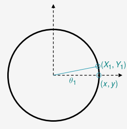
If we increase the torque the same point moves to a new location:
(X₂, Y₂)
If we use the small rotation approximation and update the location to:
(X₂, Y₂) ≈ (R, Rθ₂)
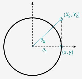
The update point is outside the surface of the shaft. This shows that the shaft has grown radially outward which is not physical. Enabling large deflection in Ansys Mechanical allows the solver to account for large rotations rather than relying on the small-rotation approximation. In this model we fix one end of the shaft and apply a large torque on the other end. In case of large strain formulation, we observe that the shaft diameter slightly decreases which is due to the Poissons’ effect. However, in case of small strain formulation, the shaft diameter increases significantly which is not physical.
Stress Stiffening
Overview
When an object undergoes large deflection in Ansys Mechanical, changes in its geometry and stiffness can significantly affect the system’s structural response.
Examples include:
- Fishing pole
- Guitar string
- Rotating parts

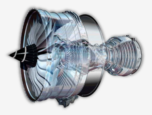
Additional Learning: Large Deformation | Ansys Innovation Courses (4-6 hours)
Guitar Example
Now consider the strings of this guitar. As we tune them the strings get stretched and stress is developed. While there may not be any big changes in the shape, there is stress developed in the part. Stress changes the stiffness of the material – stress stiffening. If we do not consider the change in stiffness, then we cannot capture the difference between a tuned and untuned guitar.

Guitarists perform tuning before any performance to have better control over the musical notes. Tuning is nothing but stretching or loosening strings to change their frequencies. When a string is stretched its stiffness increases due to stress stiffening and it vibrates with high frequency and low amplitude. When we analyze such a system, if stress stiffening is not included, we cannot capture the effect of tuning.
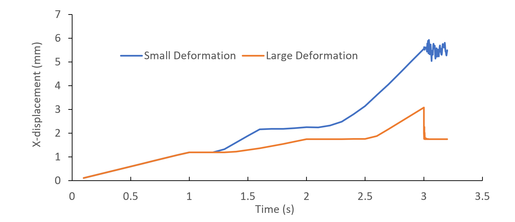
Let’s analyze how the strings vibrate when we stretch and pluck the strings. We’ll analyze this system using both small and large strain formulation. Observe how the strings stop vibrating in case of large strain formulation but continue to vibrate in case of small strain formulation.
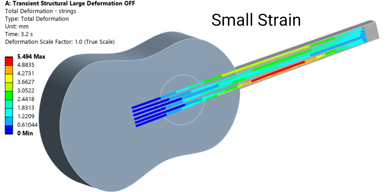
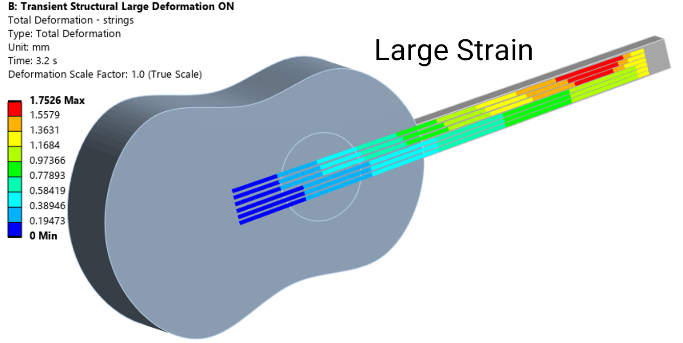
We can observe this effect when we inspect the displacement of the string over time. We pluck the string (at t = 3s) to same extent and then observe how the string vibrates freely. In case of large deformation, the string looks fairly at rest but it’s vibrating significantly. Small deformation does not consider stress stiffening so it’s ignoring the tuning effects and hence strings vibrate with higher amplitude.
Stress Stiffening Theory
This stiffening effect normally needs to be considered for thin structures with bending stiffness very small compared to axial stiffness, such as cables, thin beams, and shells and couples the in-plane and transverse displacements. This effect also augments the regular nonlinear stiffness matrix produced by large-strain or large-deflection effects
The effect of stress stiffening is accounted for by generating and then using an additional stiffness matrix, hereinafter called the “stress stiffness matrix“. The stress stiffness matrix is added to the regular stiffness matrix to give the total stiffness.
The stress stiffness matrix for 2-D and 3-D solid elements is generated using numerical integration. A 3-D solid element is used here as an example:
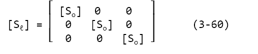
where the matrices shown in Equation 3-60 have been reordered so that first all x-direction degrees of freedom are given, then y, and then z. [So] is an 8 by 8 matrix given by:
[So] = ∫ᵥₒₗ [Sg]ᵀ [Sm][Sg] d(vol) (3-61)
The matrices used by this equation are:
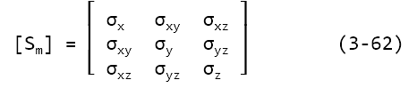
where σx, σxy etc. are stress based on the displacements of the previous iteration, and,
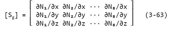
where Nᵢ represents the ith shape function. This is the stress stiffness matrix for small strain analyses. For large-strain elements in a large-strain analysis (NLGEOM,ON), the stress stiffening contribution is computed using the actual strain-displacement relationship (Equation 3-6).
[F] = [R][U] (Eq. 3-5)
where:
- [R] = rotation matrix ([R]ᵀ[R] = [I])
- [U] = right stretch (shape change) matrix
Once the stretch matrix is known, a logarithmic or Hencky strain measure is defined as:
[ε] = ℓn[U] (Eq. 3-6)
[ε] is in tensor (matrix) form here, as opposed to the usual vector form {ε}. Since [U] is a 2nd order tensor (matrix), Equation 3-6 is determined through the spectral decomposition of [U]:
[ε] = Σ(i=1 to 3) ℓnλᵢ {eᵢ}{eᵢ}ᵀ (Eq. 3-7)
where:
• λᵢ = eigenvalues of [U] (principal stretches)
• {eᵢ} = eigenvectors of [U] (principal directions)
Additional Ansys Help Documentation: 3.4. Stress Stiffening
Directory Location from Ansys Help home page:
- Mechanical APDL 2026R1\Theory Reference\3. Structures with Geometric Nonlinearities\3.4. Stress Stiffening
Spin Softening
Overview
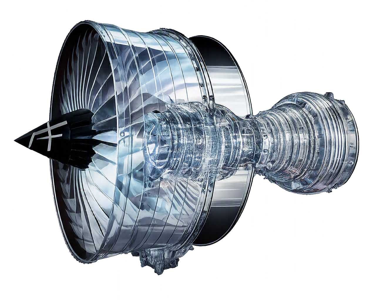
All rotating machinery experiences centrifugal forces that are acting away from the center. These forces tend to deform the components in radial direction, which changes the radius of rotation. As a result, the structure has a softer response compared to its response at rest – spin softening.
If a small strain formulation is used, this change in stiffness is not accounted for. This can be crucial in analyzing vibrational properties of rotating machinery such as wind turbine blades.

Spin Softening Theory
Rotating machinery experience large centrifugal forces that tend to deform them radially outward. Consider a deadweight M attached to a string of length l and rotated about its axis by a constant angular velocity ω. It’ll experience a centrifugal force of Ml₀ω². String stretches to new length l which changes the centrifugal force. The system eventually comes to a dynamic equilibrium.
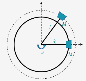
If K is the stiffness of the string, then
Ku = Mω2I
Since l = l0 + u, we can simplify this equation
(K – Mω2)u = Mω2l0
The stiffness of the system drops due to spinning − spin softening.
K’ = K – Mω2
Shape changes are not considered (spin softening ignored) when using small strain formulation. Consequence of ignoring spin softening is that the system is overly stiff compared to reality. Usually spin softening and stress stiffening act in tandem as shown for the turbine blade scenario in the table below showing the effects of both.
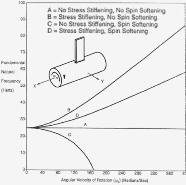
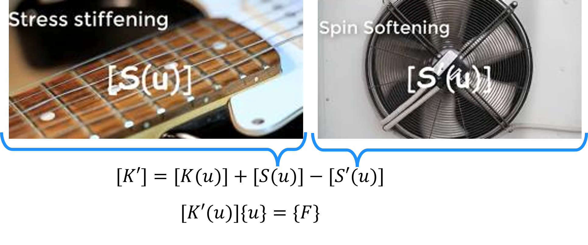
Depending on which phenomenon dominates, the stiffness of the system may increase or decrease compared to a small-strain formulation. Large deflection in Ansys Mechanical accounts for additional effects, including stress stiffening (S) and spin softening (S′), which contribute to the total stiffness and depend on the system’s displacements. Adding these terms to the governing equations:
K’ = K({u}) + S({u}) – S'({u})
Overall, the stiffness matrix becomes a function of system displacements, and the equation is no longer linear in nature.
[K({u})+S({u})-S'({u})]{u}={F}
This is how the large strain formulation makes the governing equation nonlinear.
Prestressed Modal Example
- Bladed fixed at center undergoing rotational velocity
- Prestress modal analyses solved with large deflection on and off
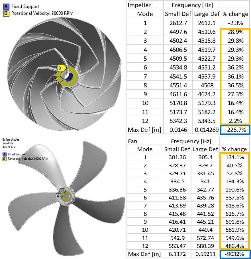
Large deflection causes:
- Increase in natural frequency
- Decrease in deflection in the pre-stress static structural result
Large Deflection in Ansys Mechanical: In Summary
Large deflection/deformation analysis is important in Ansys Mechanical simulations when geometry changes significantly or stress alters structural stiffness. Enabling the Large Deflection setting in Mechanical within the Analysis Settings allows the solver to account for geometric nonlinearities that a small-strain or small-rotation formulation may miss.
Geometric nonlinearities refer to the nonlinearities in the structure or component due to the changing geometry as it deflects. That is, the stiffness [K] is a function of the displacements {u}. The stiffness changes because the shape changes and/or the material rotates. The large deflection setting accounts for four types of geometric nonlinearities:
- Large strain (fishing rod) significant bending changes the geometry and load response.
- Large rotation (drive shaft) small-rotation assumptions can predict unrealistic radial growth.
- Stress stiffening (guitar string) tension changes stiffness and vibration behavior.
- Spin softening (rotating machinery such as turbine blades) centrifugal effects can reduce effective stiffness.
Structural stiffness can depend on displacement, shape change, rotation, stress state, and rotational speed. When these effects are meaningful, large deflection analysis provides a more realistic prediction of deformation, stiffness, vibration response, and overall mechanical behavior than a purely linear small-deformation approach.
Take Your Nonlinear Analysis Skills Further
Looking to build your confidence with nonlinear structural simulations? SimuTech Group’s Ansys Workbench Mechanical Structural Nonlinearities (FEA 102) training explores nonlinear procedures, contact formulations, diagnostics, and advanced analysis techniques.

Kohl Schoensee
Staff Engineer
Kohl Schoensee is a Staff Engineer at SimuTech Group with a bachelor’s degree, with honors, in mechanical engineering from the University of Utah. He specializes in topology optimization, structural nonlinearities, and aerospace applications. His notable project experience includes topology optimization mentoring for 3D-printed Formula SAE suspension uprights, large-deformation analysis of hyperelastic pipeline cleaning PIGs and seal mechanisms, fatigue analysis of helicopter components, and shock and random vibration analysis of missile components.