Measuring Face Translation and Rotation in Ansys Mechanical
Ansys Mechanical Workbench supports Deformation Probes, which on solid bodies can measure UX, UY, UZ and USUM of geometry or Remote Points. They do not (directly) measure rotation.
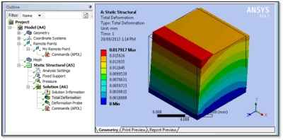
This article illustrates how to use APDL commands to refer to an existing Remote Point, and measure translation and rotation at the point. If the remote point interacts with a face that is set to Deformable, an averaged value of face movement is measured. If there is no load on the remote point, movement is measured without affecting the result.
As an alternative, users could employ a General Body-Ground joint attached to the face of interest, free all degrees of freedom, and use a Joint Probe to measure Relative Rotation This avoids APDL commands.
Deformation Probe in Ansys Workbench
Workbench Mechanical has a Deformation Probe object for postprocessing.
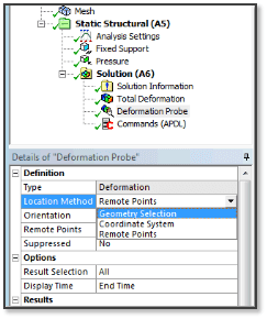
The Deformation Probe supports a non-default choice of Remote Points as location for the measurement of deformation. If a Remote Point associated surface behavior is set to Deformable, an average deformation of the surface can be measured for the Remote Point without affecting the model:
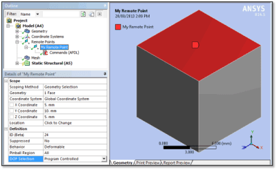
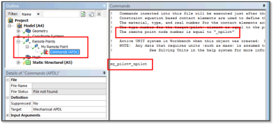
An APDL Commands Object at a Remote Point branch accesses the remote point’s node, identified with the parameter “_npilot”. In the following example, the node is remembered as “my_pilot”, since “_npilot” us updated with each Remote Point that is defined. Parameter “my_pilot” is used later in a postprocessing APDL Commands Object to measure movement and rotation. A one-line entry in the APDL Commands Object is sufficient:
my_pilot=_npilot
Deformation Probe Measuring all but Rotation
The next figure shows a Deformation Probe that measures UX, UY, UZ and USUM but not rotation:
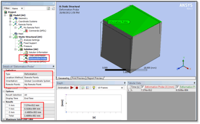
A postprocessing APDL Commands Object can measure the rotation of the node “my_pilot” as identified at the Remote Point branch above, as well as Time of the result. Here are the APDL Commands:
*get,my_ux,node,my_pilot,u,x
*get,my_uy,node,my_pilot,u,y
*get,my_uz,node,my_pilot,u,z
*get,my_usum,node,my_pilot,u,sum
*get,my_rotx,node,my_pilot,rot,x
*get,my_roty,node,my_pilot,rot,y
*get,my_rotz,node,my_pilot,rot,z
/com, Convert radians to degrees
pi=acos(-1)
my_rotx=my_rotx*180/pi
my_roty=my_roty*180/pi
my_rotz=my_rotz*180/pi
/com, Time of the result
*get,my_time,ACTIVE,,SET,TIME ! time of result in database
Results are displayed as illustrated in the next figure:
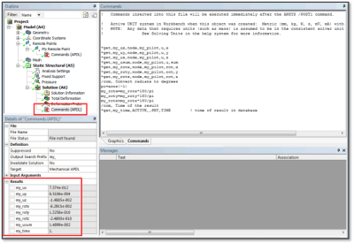
Users must be aware of the Units employed in solution in reading the translation Results above, and that these rotations have been converted to Degrees. Results have been extracted for whatever is in the Ansys database when commands are executed. SET commands are needed in the APDL script to specify other load steps, substeps, or times of interest. Input Arguments could pass values to a SET command in the script.
Surface Construction Geometry Technique
A result that is measured with a Surface created within Construction Geometry can be used to report a result where the Surface cuts across one or more bodies. The surface has to touch elements of the bodies.
The figure below has used a user-defined coordinate system “My_Coordinate System” to cut across the top face of the body. A Directional Deformation in Z has been measured on the Surface. In the Details of the Directional Deformation result, Maximum, Minimum and Average deflection in Z are reported. This technique does not report the rotation, however.
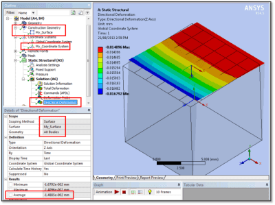
Note that the Average reported above matches the Z movement measured by other techniques in this article. This is part of the indirect method for measuring face translation and rotation in Ansys.
The above use of a Remote Point does not report an average Temperature in a thermal analysis. A Surface as above will report an average temperature where the Surface cuts across the elements of one or more bodies. Another APDL technique can be used to generate average temperatures for selected faces, and has been described in a previous article.
To measure an averaged rotation, a General Body-Ground joint can be attached to the face of interest. The user frees all degrees of freedom in the joint, and uses a Joint Probe to measure Relative Rotation setting what is reported to “All”. The Behavior of the selected face is set to deformable. The following figure illustrates settings and the result:
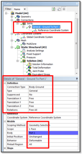
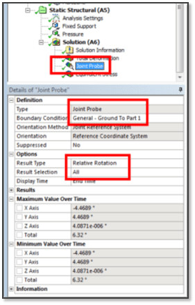
Note that the Pinball Region above is set to “All”. A finite value here can restrict how much of the surface is included in forming the average.
With either the Remote Point approach, or a General Joint approach, choosing a face with a large number of nodes will increase wavefront during Solve, and will result in a longer solution time. A finite pinball diameter can restrict how many nodes are involved.
Conclusions | Measuring Face Translation and Rotation
Workbench Mechanical supports a Deformation Probe that can scope to a Remote Point to measure movements at a face on a model. If the associated face is set to Deformable at the Remote Point definition, then an averaged value can be measured on the face without affecting the model.
Deformation Probes do not currently support measurement of rotation. APDL Commands Objects can record the node number of the Remote Point of interest, and in postprocessing can measure translations and rotations of the remote point.
As shown below, the same translations are returned by a Deformation Probe and an APDL Commands Object:
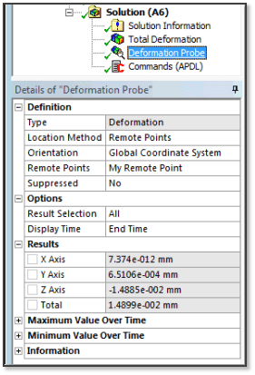
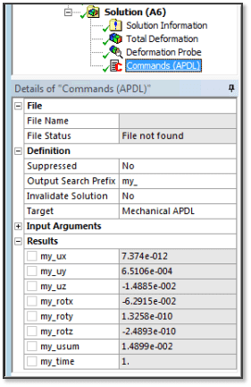
Note that the measured rotations above have been converted to Degrees by APDL Commands, and that no Units are displayed in the Results of the APDL Commands. This conforms to the rotation convention employed in Ansys.
When a General Joint is employed for the measurement, not APDL commands are needed, and the units for the Probe results are automatically set.


