A common question asked by Lumerical designers is regarding the best method to export their design geometry for fabrication. Some design teams prefer to create devices in the layout first and import to Lumerical as a secondary step. However, the workflow is more complex as it would require familiarity with the layout software, and designers would need to rapidly switch between two software when exploring the design space.
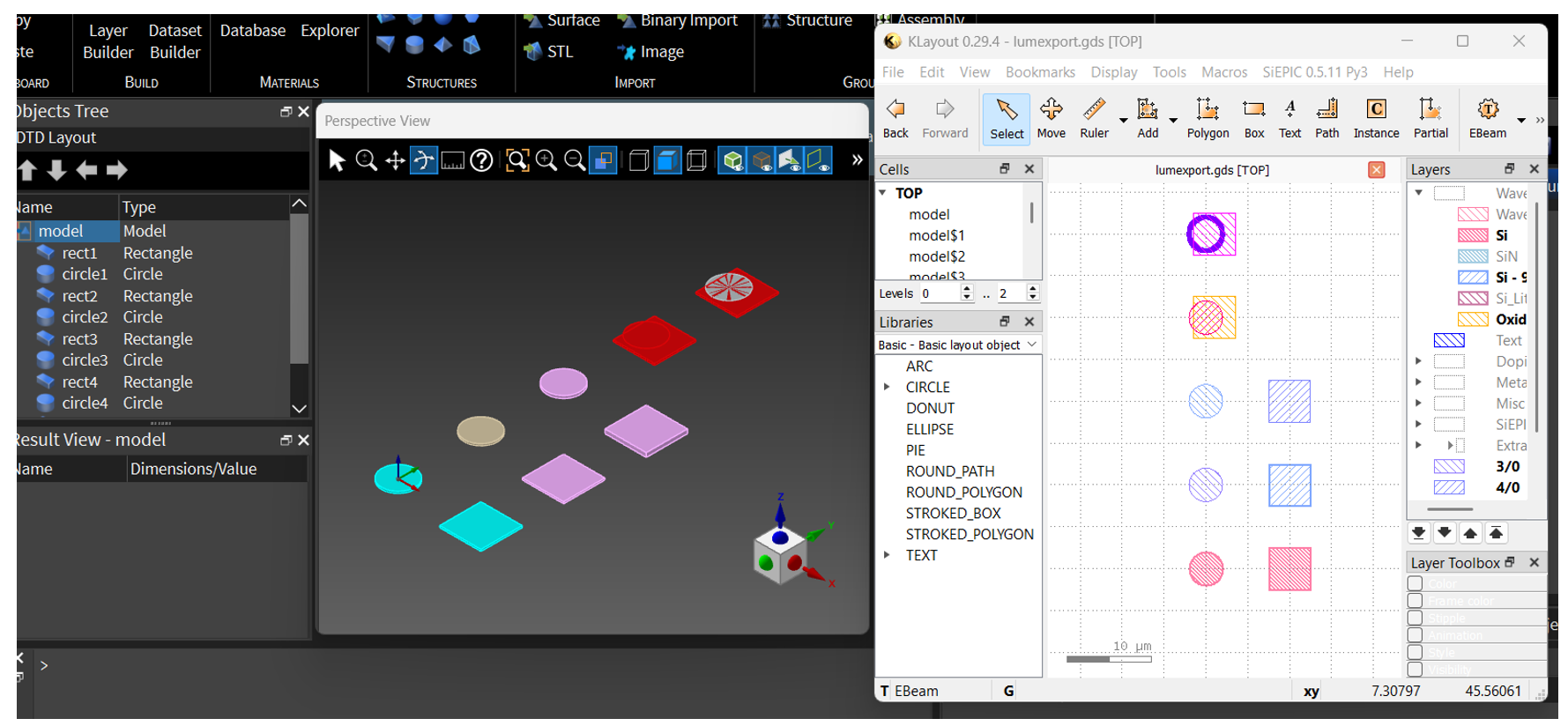
Alternatively, users can export directly from Lumerical into a GDS file. The Lumerical APP gallery has an example demonstrating this procedure available at (In the next sections, we will walk through different methods to using this library, and the situations they are best suited for.
Exporting through Lumerical Script
The first method to export is done using Lumerical Scripts [1]. This method is possible by importing an encrypted library file (GDSexport_core.lsfx) provided by the Ansys Lumerical development team. The encrypted file includes backend functions that aren’t accessible to users by default.
This method is a manual export process and is best suited for small exports or if high amounts of customization for exporting are necessary. The drawback of this method is that each object, height, and material needs to be manually defined.
This method has the following steps:
- Define the layer export information in a structure dataset.
- Pass the dataset to the encrypted function to generate a GDS.
The structure dataset requires the following information that cannot be omitted:
layer_1 = struct;
layer_1.z = 0.0e-6;
layer_1.material = "Au (Gold) - CRC";
layer_1.layer = "1:0";- Line 2 is the z axis location where the 2D topography will be extracting from. This is because layouts are 2D, so 3D objects will need to specify the 2D plane for the geometry to export.
- Line 3 is the material in Lumerical’s format. This acts as a filter to extract only the objects that contain the chosen material.
- Line 4 is the layout layer information to export to. This is a standard specification for layout files. You can read more about this from layout programs such as KLayout [2]. The layer and datatype are in the “X:Y” format, separated by a semicolon. The numbers are mappings for fabrication layers which are defined by your chosen foundry.
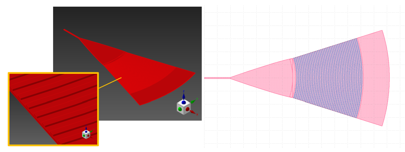
Once the export information is defined, the dataset can be used as input in the scripts to generate a GDSII:
Exporting through UI
Files and instructions available at: SimuTech’s GitHub
We understand not all users find the declaration of datasets straightforward and instead prefer that an interface method exists. As such, our scripting and automation team at SimuTech Group has created an addon component, named “LumToGDS”, that helps streamline and automate the exporting process [3].
This second method is a process is suitable for suitable for complex geometry exports where many of the objects are on similar layers. This method is also suitable for designers who prefer an interface approach rather than a fully scripted procedure.
To use this method, users simply run the addon and a wizard interface will pop up to prompt the export information:
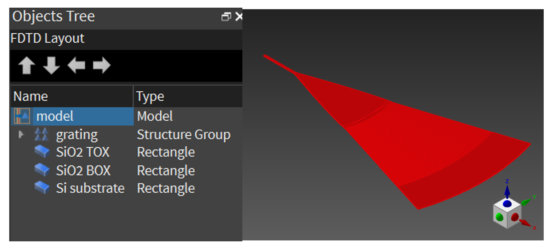
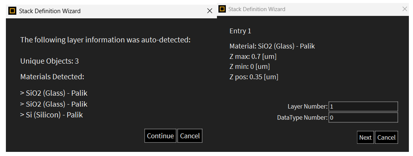
The wizard automatically detects geometry objects that can be exported.
To streamline the process, the wizard will also group objects on the same material at the same height location together. If the user assigns export information to once, it will be applied to all relevant objects.
Users can also step back in the wizard via the ‘Cancel’ button to correct any mistakes.
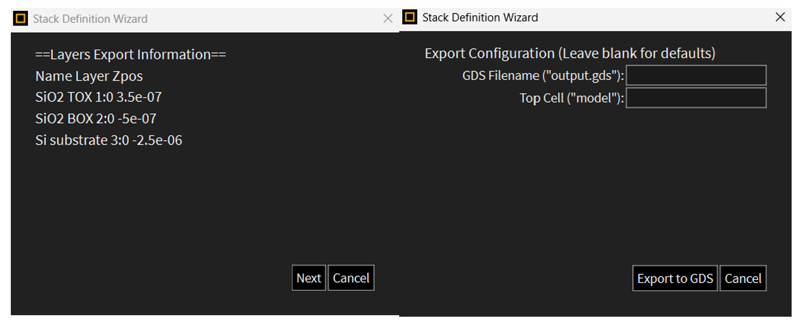
If all the information looks correct, simply click “Export to GDS” on the final page of the wizard and the GDS file will be generated:
Exporting through Python
Files and instructions available at: SimuTech’s GitHub
We understand that for expert designers, the ability to integrate procedures into automated workflows is a significant cost saving. As such, LumToGDS also includes a python class allowing for easy integration into any python workflow.
This third method of exporting to GDS is suitable for advance users who are looking to fully automate their export process.
To access the python interface, simply launch the python class LumToGDS.py which automatically runs the following code:
myexport = LumToGDS()
myexport.main()
Here, we instantiate a LumToGDS as an object named `myexport`. We can then call the main() function which will run the python interface:
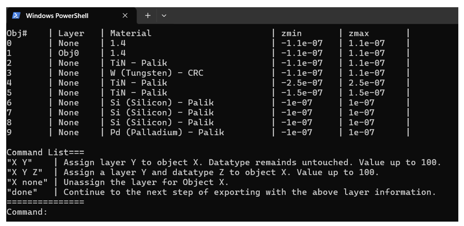
The python interface can be used for fast conversion from Lumerical simulation to a GDS. You can quickly set object layer numbers, and the interface will update them in real time. When ready, the ‘done’ command will generate the GDS.
The target file, output file, and other settings are available through the declared object, allowing for multiple instances and modularity:
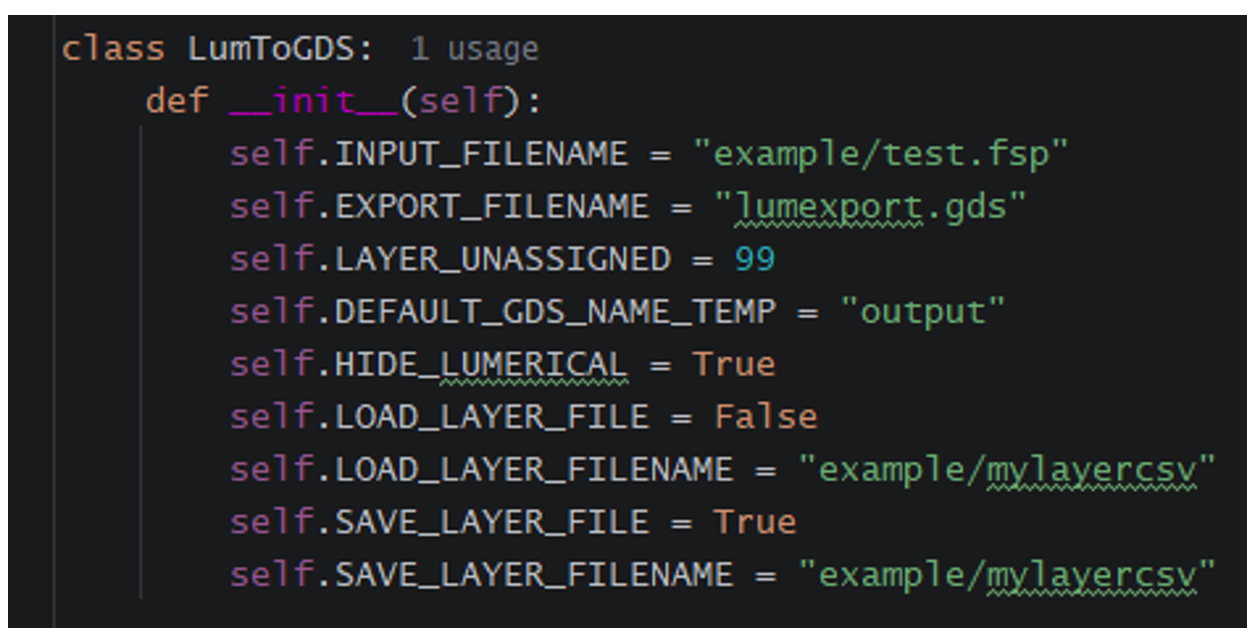
The python class also allows predefined layers to be saved to a CSV file. The layer file contains each object line and the destined layer/datatype to export to. This feature is useful for automation of repeatedly exporting a device type, as there will be many parameter changes, but the stack is not changing.
For complex workflows, the LumToGDS library can be imported as a library and its sub-functions called separately; This includes getting object metadata from Lumerical, assigning layers, and exporting to a GDS file.

Looking to streamline photonic design-to-layout workflows in Ansys Lumerical?
Talk with SimuTech Group about photonics simulation, GDS export automation, and expert support for more efficient device development.

Stephen Lin, MASc, Electrical Engineering/Silicon Photonics
Photonics Staff Engineer, SimuTech Group
Stephen Lin has six years of experience in Silicon Photonics design and PDK development and is well-versed in industry standard software, including Ansys Lumerical, Ansys Zemax OpticStudio, Mentor Graphics Pyxis & Calibre, and SiEPIC PDK/Tools. He is skilled in foundry submission process (DRC, foundry layers, etc.), and has long-time interest in multi-physics and co-simulation of photonic systems.
- Ansys, GDSII Export Automation. https://optics.ansys.com/hc/en-us/articles/1500006203341-GDSII-Export-Automation
- KLayout, About Layer Specifications. https://www.klayout.de/doc/about/layer_specs.html
- SimuTech Group, https://github.com/simutechphotonics/LumToGDS