Summary
In the world of finite element analysis, one of the larger challenges relates to the obtainment of meaningful and actionable material properties. When working with adhesives, engineering analysts depend on product vendor material datasheets, which provide minimal information.
The purpose here is to define and validate a process to convert the “Tensile Lap Shear Strength” (typically provided in material datasheets for adhesives) into an actionable “maximum out-of-plane shear stress.”
The adhesive allowable stress can then be compared directly to finite element analysis results for arbitrary configurations using the same adhesive.
Details
To understand the joint and adhesive behaviors and to determine design-allowable stresses which can be applied to structural joints bonded with an adhesive, we will reference a specific film adhesive, such as LOCTITE ABLESTIK CF 3350. However, the process identified in the discussion can be applied to any adhesive which is characterized by the “Tensile Lap Shear Strength.” The datasheet for this adhesive indicates that the Tensile Lap Shear Strength is derived from an ASTM D1002 test joint experiment.
This ASTM experiment is meant to illustrate relative strength between different adhesives but not necessarily used to describe an actual strength that could be used within a finite element analysis evaluation. This same ASTM standard makes the following statement about Tensile Lap Shear Strength:
“The apparent shear strength measured with a single-lap specimen is not suitable for determining design-allowable stresses for designing structural joints that differ in any manner from the joints tested without thorough analysis and understanding of the joint and adhesive behaviors.”
Therefore, within this discussion, we will perform a thorough analysis and develop an understanding of the joint and adhesive behaviors.
Background Information
LOCTITE ABLESTIK CF 3350 is a film adhesive formulated for electrical, thermal and mechanical assembly applications.
Loctite (Henkel) provides, in their “LOCTITE-ABLESTIK-CF-3350-en_GL.pdf” data sheet, the following reference to the Tensile Lap Shear Strength:
- Tensile Lap Shear Strength 3,400 Psi when bonding Aluminum to aluminum while considering 4 mil thickness and tested at @ 25ºC.
Tensile Lap Shear Strength is evaluated using ASTM D1002: “Standard Test Method for Apparent Shear Strength of Single-Lap-Joint Adhesively Bonded Metal Specimens by Tension Loading (Metal-to-Metal)”. Therefore, finite element models of the ASTM D1002 Lap Joint are created to evaluate the state of stress that occurs under small deformation analysis conditions so that design allowable shear stresses can be applied and determine if shear failure is of a concern.
To accomplish this goal:
- A series of analyses are performed utilizing different mesh sizing so that average and peak allowable stresses can be extracted,
- The component stresses are reviewed to determine candidates for allowable stress characterization,
- Mesh and geometry characteristics are evaluated toward developing mesh independent allowable stress characterization, and
- Linear interpolation is applied to provide allowable average and maximum out-of-plane shear stresses which correlate directly to analysis data.
ASTM D1002 Lap Joint
The image bellow illustrates the ASTM D1002 Lap Joint test specimen, where “L” represents a 12.7mm overlap.
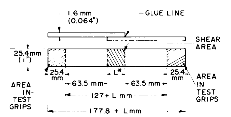
The ASTM specification provides for aluminum and recommends Alloy 2024 with a T3 temper. All analyses will be performed for the 25C testing temperature.
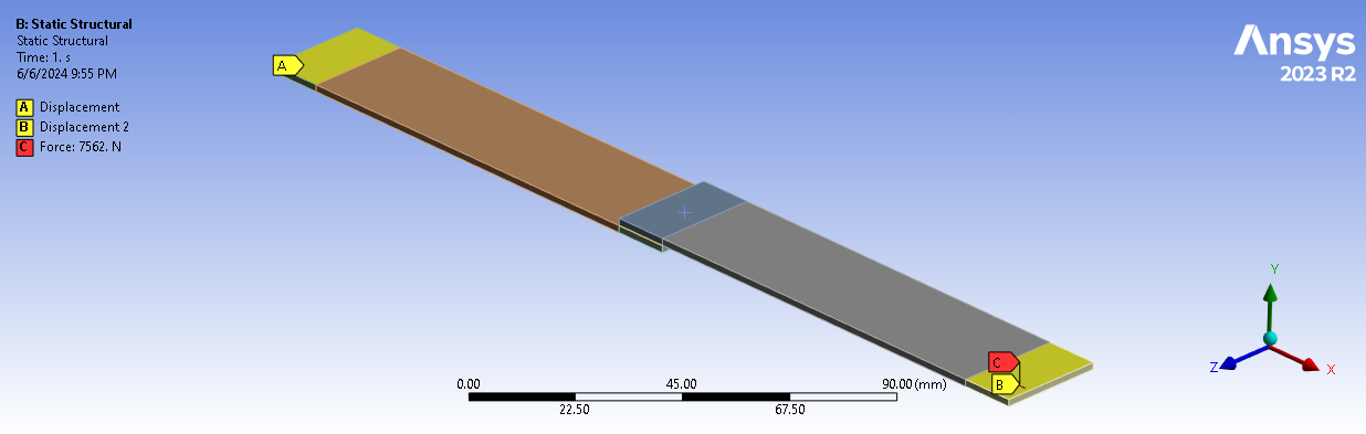
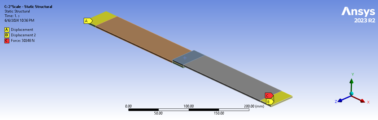
ASTM D1002 – FEA Model Description
A finite element model was constructed in Ansys Mechanical to replicate the ASTM D1002 testing apparatus and the operating temperature (25C) and adhesive thickness of 4 mils was utilized to reflect the Loctite data sheet testing specifications.
At 25C, Loctite predicted 3400 PSI lap shear strength (or 23.44 MPa).
Multiplying this strength times the shear area arrives at 1700 lb (or 7562N). This tensile load will be applied to one end of the fixture, while the opposite end is fixed from any movement. Both ends are held in their original planes to replicate the test fixture.
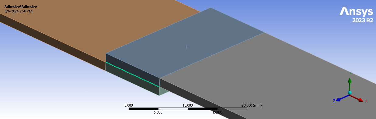
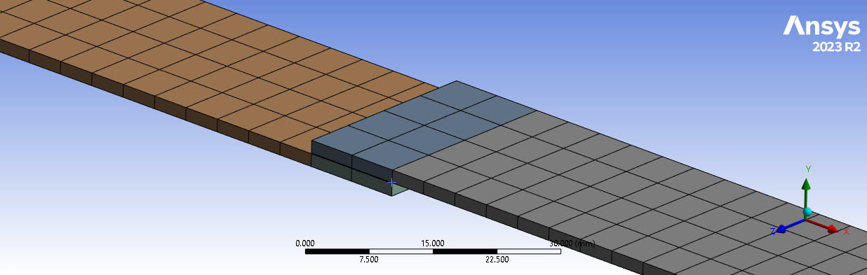
Mesh Density for Adhesive Allowable Stress
The following two images illustrate two different meshes on the adhesive region, ranging from a 2×4 mesh pattern, to a 64×128 mesh pattern.
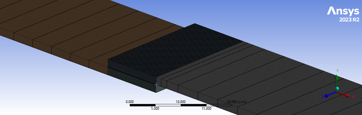
By exploring how stresses change based on mesh size allows us to predict allowable strength values based on different models having a different mesh size but still utilizing a similar relative mesh size to our collection of analyses.
Six different mesh densities were explored: 2×4, 4×8, 8×16, 16×32, 32×64 and 64×128.


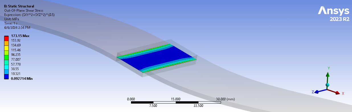
Summary: Out-of-Plane Shear Stress
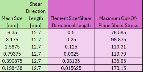
The table below summarizes those minimum, maximum and average out-of-plane shear stresses collected from the adhesive while considering different mesh densities.

These analyses show that the average stress is highest for the coarsest relative mesh size, while the highest maximum stress occurs for the finest relative mesh size.
Because the stresses do not converge with mesh size, this workflow requires analysts to understand the relative mesh size when deriving an adhesive allowable stress for models in Ansys Mechanical.
Mid-Thickness Linear Out-of-Plane Shear Stress
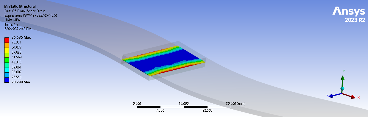
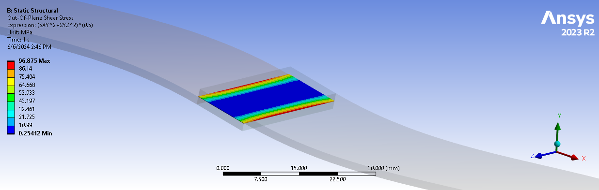
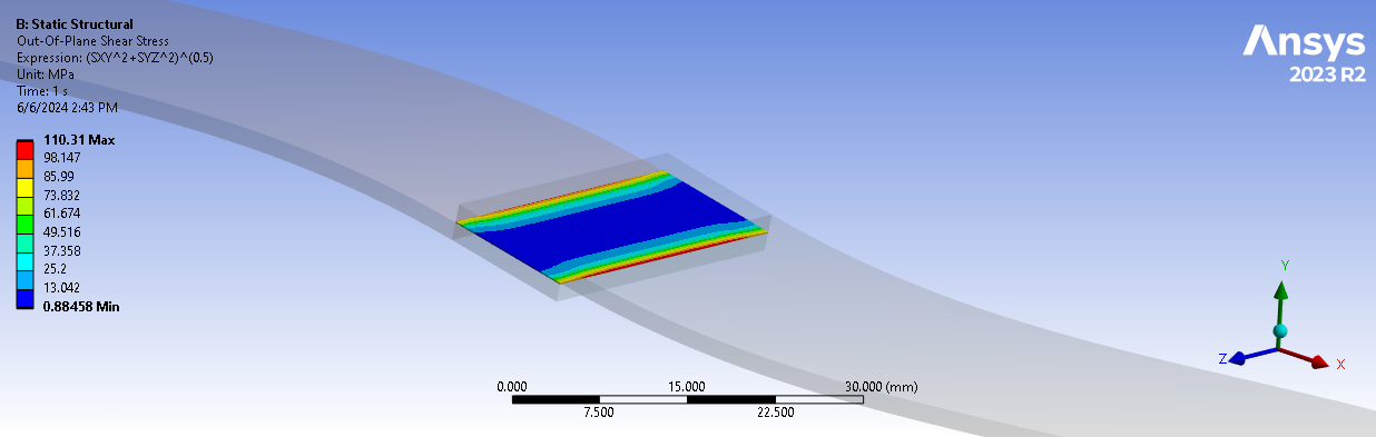
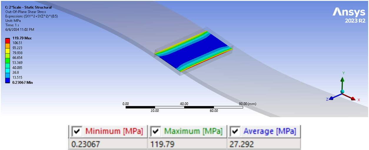
The following two images examine the out-of-plane shear stress in the direction of the tensile force to better understand the relationship between average and maximum stress as the mesh density changes.

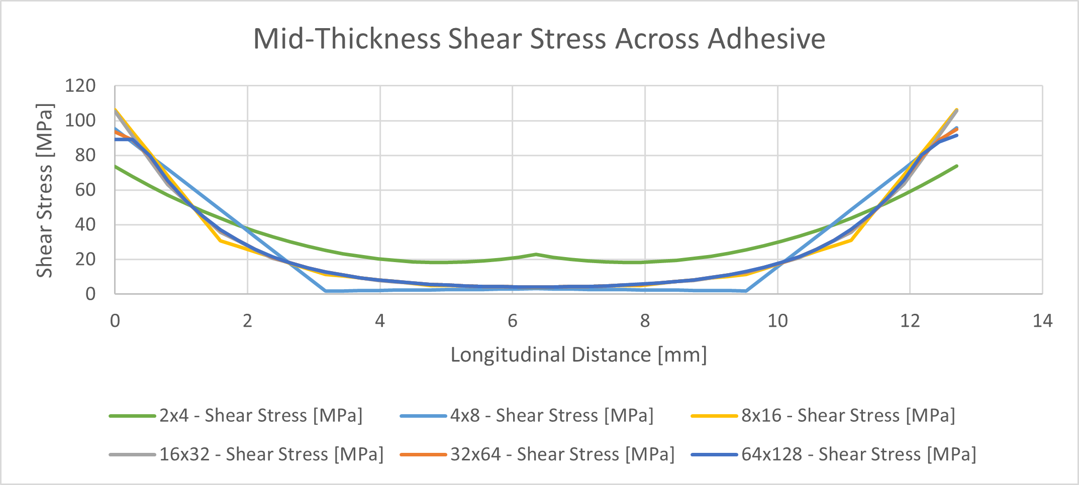
It should be noted that the out-of-plane shear stress is the square root sum of the squares of the two out-of-plane shear stress components, SXY and SYZ. Because of this combination method, all values are positive.
As the mesh density increases, the mid-span stresses approach zero, while the edge stresses approach infinity.
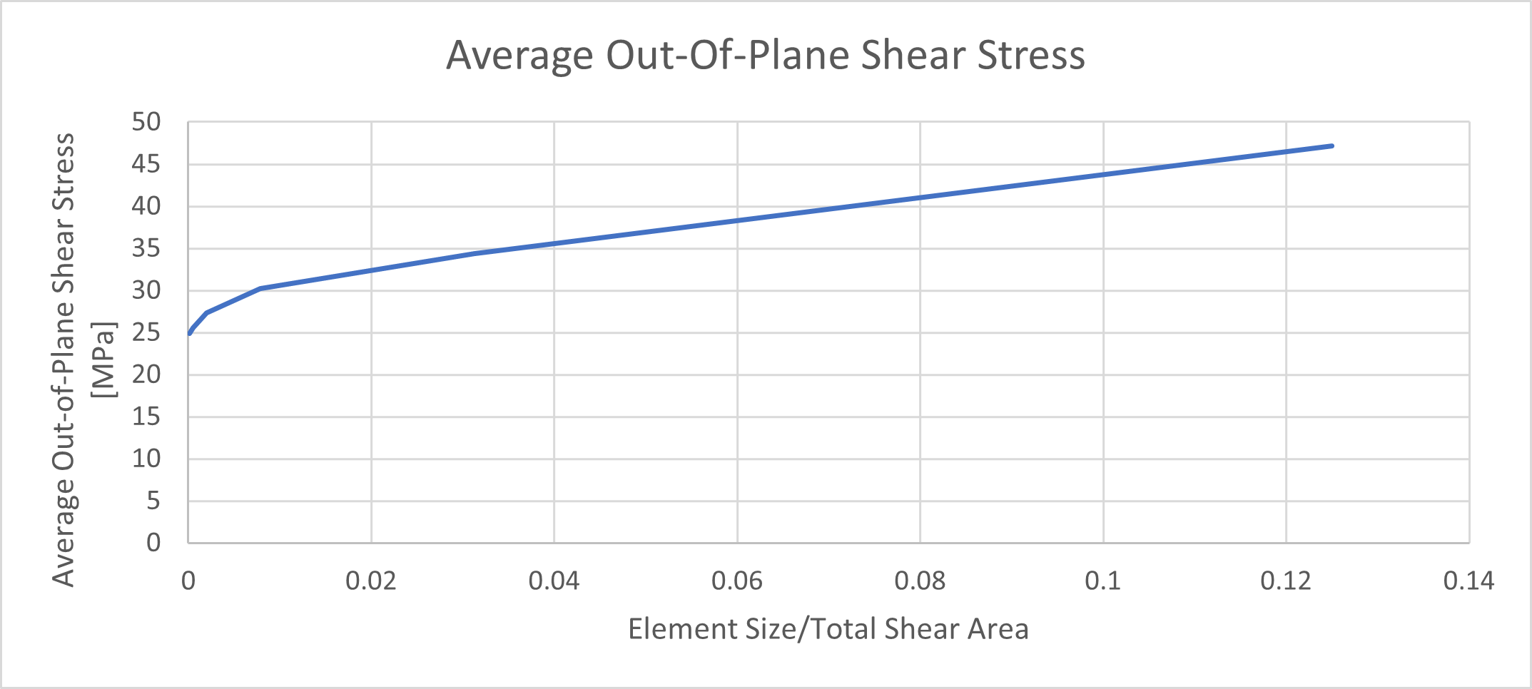
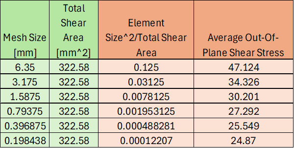
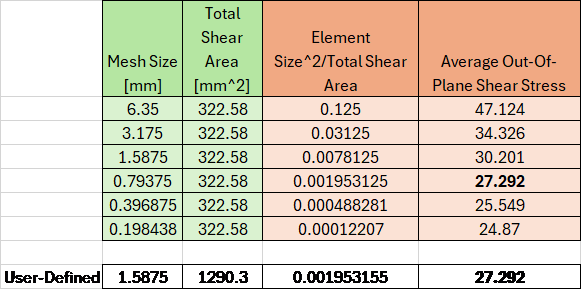
One can see that the calculation of average stress across the entire body shows a mostly linear relationship to mesh size. However, if we hope to apply an allowable average stress for use in other finite element models using different geometry, then we need to characterize the element size^2 relative to the shear area.
Using this method, one can linearly interpolate from this table based on element size^2 relative to the total shear area to arrive at an Average Allowable Out-of-Plane Shear Stress.
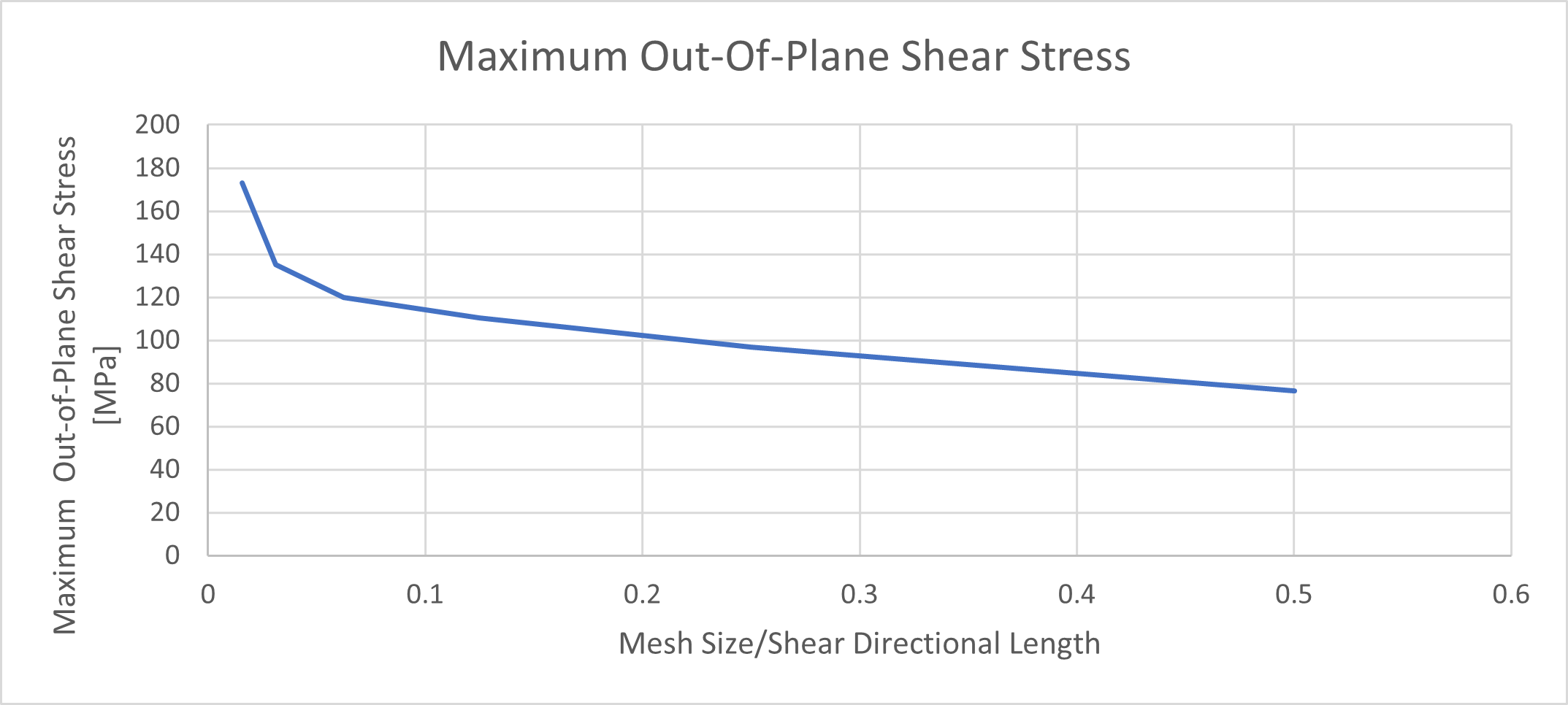
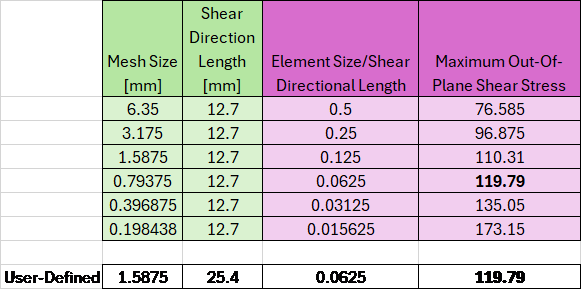
One can see that the calculation of maximum adhesive allowable stress across the entire body shows an exponential relationship to mesh size. This is a non-convergent stress behavior. If we hope to apply an allowable maximum stress for use in other finite element models using different geometry, then we need to characterize the Element Size/Shear Directional Length.
Using this method, one can linearly interpolate from this table based on Element Size/Shear Directional Length to arrive at a Maximum Allowable Out-of-Plane Shear Stress.
It should be noted that the Shear Directional Length may be subjective depending on the type of loading and can be considered analogous to the characteristic length associated with a Reynolds Number calculation.
Allowable Stress Confirmation
Based on the scaled model’s mesh size and shear area, one can calculate the proportionality factor of 0.001953, which corresponds to an average out-of-plane shear stress of 27.292 MPa, which matches our new model’s results.
The same is true for the maximum out-of-plane shear stress interpolation based on the element size/directional length, corresponding to 119.79 MPa.
Adhesive Allowable Stress Conclusion
We replicated the ASTM D1002 testing method and varied the mesh size to establish a table of average and maximum out-of-plane shear stresses, then developed unitless constants based on mesh size and geometry characteristics so that these mesh dependent stresses can be used as allowable shear strength values for different configurations using this same adhesive.
We performed a verification model which was guaranteed to produce the same result as the original test model to show our dimensionless constants would correctly estimate the correct shear stress values.
This example demonstrates that we can confidently apply these allowable stresses for new geometries while evaluating the proximity to failure for this particular Loctite adhesive.
Need help evaluating bonded joints, adhesive performance, or structural failure risk in Ansys Mechanical? SimuTech Group’s FEA consulting experts can help your team develop practical simulation workflows, interpret stress results, and make better-informed design decisions.

Patrick Tessaro, P.E.
Senior Application Engineer, SimuTech Group
Pat Tessaro, P.E., is a Senior Application Engineer and Structures Team Manager at SimuTech Group, where he supports customers using Ansys simulation tools for structural and mechanical analysis. Pat brings more than 20 years of engineering experience to his work, including deep expertise in finite element analysis, simulation workflow development, technical support, training, and consulting. His background helps engineering teams turn complex analysis challenges into practical, simulation-driven solutions.