Contact Us
Introduction to Ansys Electronics Transformer ACT
In this blog I discuss how to use the Ansys Electronic Transformer ACT to automatically and quickly design a power electronics inductor or transformer. I will go through the steps to design and create an example of a power electronics transformer, concentric component, two winding, excited with sinusoidal voltage excitation, with load and frequency sweeps applied. By default this ACT setups an Eddy Current study in Maxwell but this can easily be changed for a Transient or Magnetostatic study.
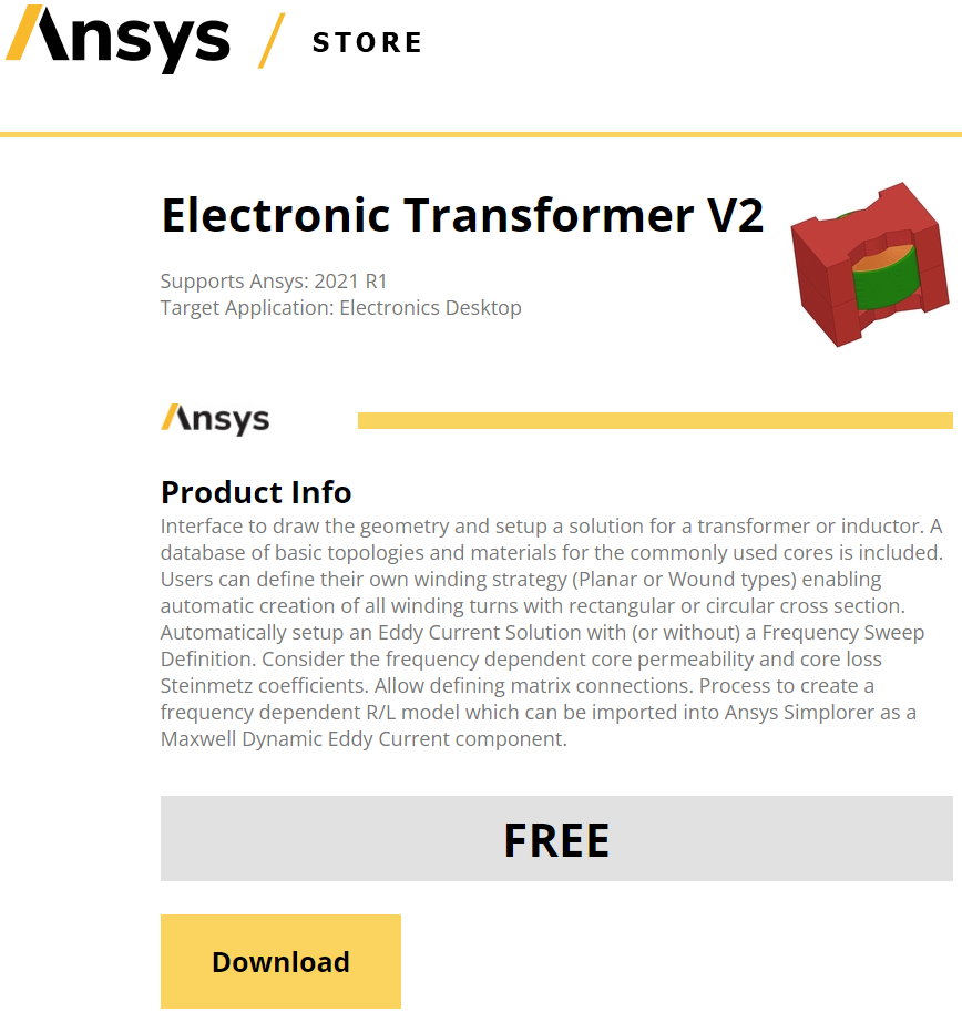
Download the Ansys Electronic Transformer ACT from the Ansys ACT store via the link below
https://catalog.ansys.com/
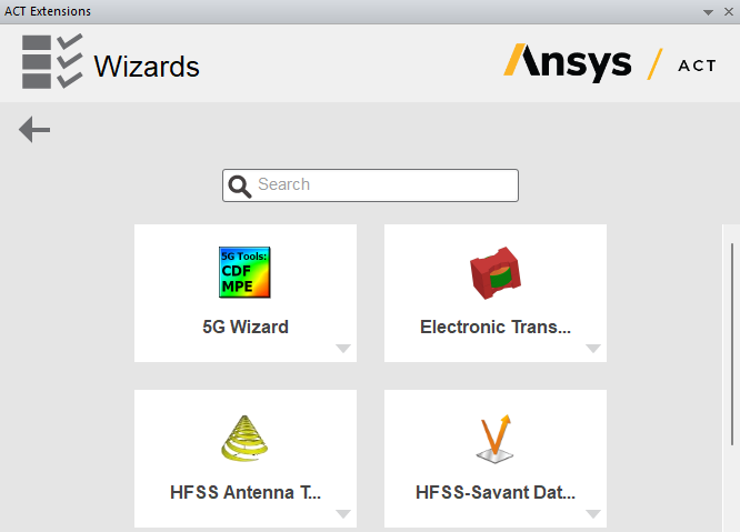
After downloading the Ansys Electronic Transformer ACT open a Maxwell project, go to “View”, select “ACT Extensions”, and launch the ACT Wizard. Select the Electronics Transformer ACT
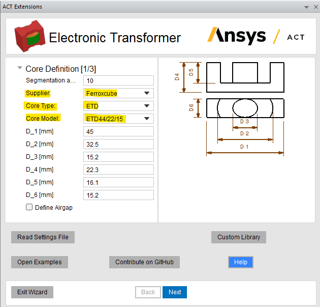
There are three panels of settings to complete to build a 3D FEM model of an inductor or transformer with the Electronic Transformer ACT. The core is defined in panel one, the windings are defined in panel two, and the Analysis setup is defined in panel three.
The Ansys Electronics Transformer ACT user’s manual can be obtained by selecting “Help” on the bottom right of the panel as shown below.
Panel 1:
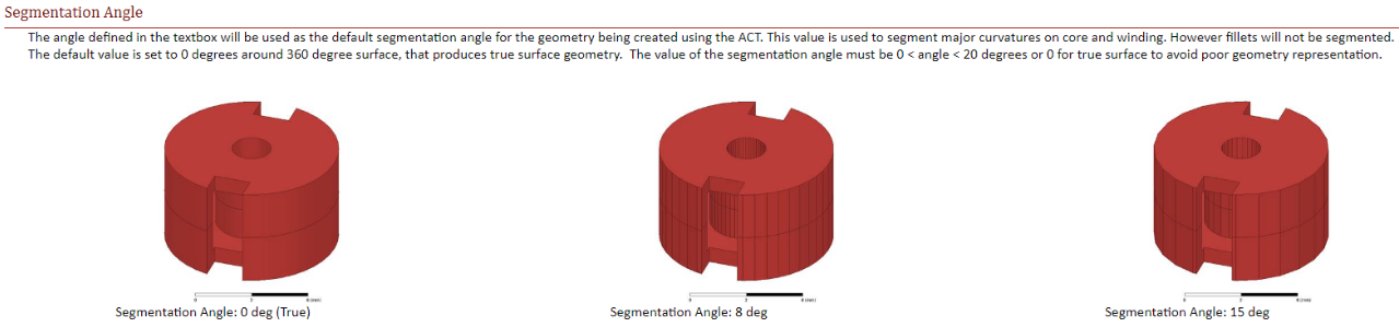
There are multiple manufacturers to choose from and 15 core types available to choose. The specification sheets for the cores can be found online via the manufacturer’s website. Resolution of curved geometry is defined by the segmentation angle and should be a value between 0 and 20, and using a small value results in more accurate geometry creation, but is more costly computationally. We can leave the air-gap definition unchecked or we can select this definition and choose settings for the air-gap dimensions and determine if the air-gap is on the center leg or on the side legs.
Panel 2:
The transformer can be wound or planar, and the conductor type can be circular or rectangular. Select the number of layers (windings).
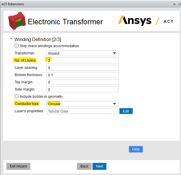
Select “Layer’s Properties” to define the conductor dimensions, number of segments, number of turns, and insulation thickness. Apply 2.588 mm to design AWG wires.

Panel 3:
Select “Make Full Model” to create a full model or leave unchecked to create a half symmetry model.
Select the “Core Material” drop down and choose the core material. The excitation can be “Voltage” or “Current”.
Select “Side Loads” to define the load connected across the secondary.
Leave “Create skin layers for mesh” unchecked and read the manual for more information about this selection.
If designing an inductor then choose one transformer side. In this example I have selected “two” transformer sides.
A frequency sweep can be defined here or can be defined in “Analysis Setup” in Maxwell after the model is created.
The design will be saved as a JSON file in the “Save” to location defined.
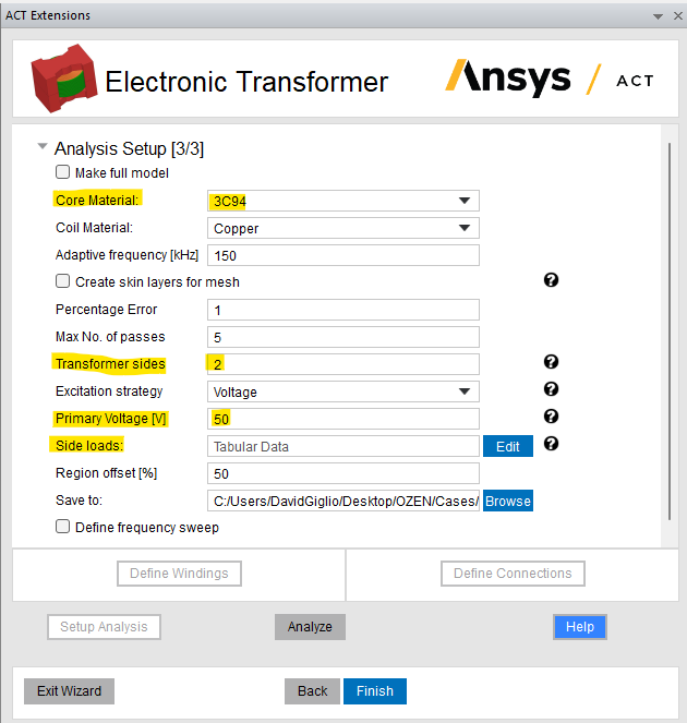
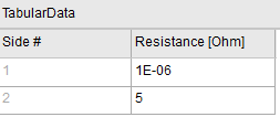
Select “Side loads” and apply 5 Ohms for the load connected on side #2 to design the transformer deliver 250 W.
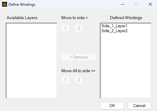
Select “Define Windings” and move “Layer 1” to “Side 1” and “Layer 2” to “Side 2”. You can create as many windings that can fit in the winding window of the core you selected, and you can move the windings to the desired side.
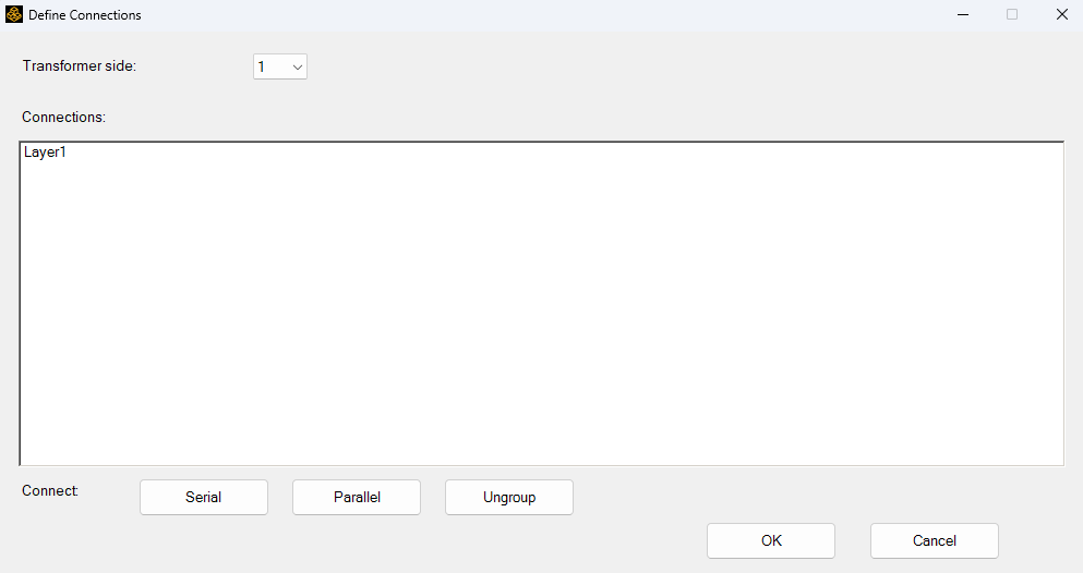
Select “Define Connections” and make winding connections. If there were more than one winding in a side then we would have to connect them in series, parallel, or ungroup (undo) a connection. In this example there are only two “Layers” (windings) and only two “Sides” so there are no connections to be made so click “OK”.
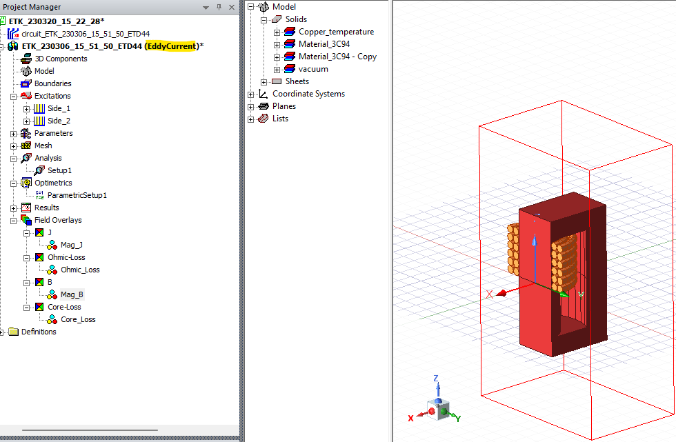
Maxwell Model
By default this ACT setups an Eddy Current study in Maxwell but this can easily be changed for a Transient or Magnetostatic study, as mentioned above, in the beginning.
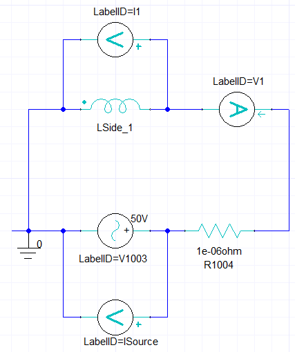
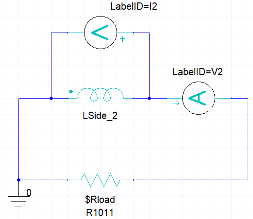
Maxwell Circuit Model – External Circuit Excitation
The Ansys Electronics Transformer ACT sets up a Maxwell External Circuit for the excitation and uses the “Voltage” or “Current” excitation value you defined in “Panel 3”. By default there are no probes applied but you can easily add these as desired.
PRIMARY SECONDARY
Maxwell Model – Geometry
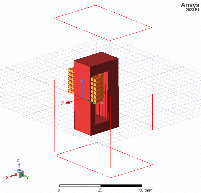
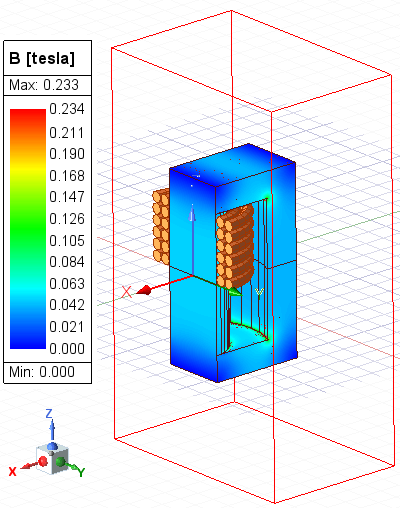
Observe the half symmetry of the model and that there are two windings with six turns each as designed.
Maxwell Model – Frequency Sweep
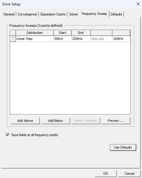
The frequency sweep could have been defined in “Panel 3” of Ansys Electronics Transformer ACT or could be defined in “Analysis Setup” in Maxwell as mentioned above, and in both definitions the same setup options are available. We can choose various distributions for the sweep.
Maxwell Model – BH Curve
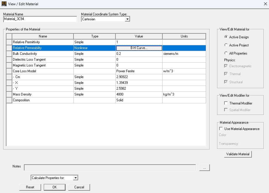
This design uses a non-linear B-H curve. It is simple to change from a linear B-H curve to a non-linear curve. Select the “Core” material, select “Edit” in the material properties, select “Relative Permeability”, and under “Type” choose Nonlinear. Then under “Value” choose B-H Curve.
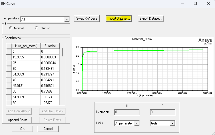
Select “Import Dataset” to import a B-H curve file (type .tab). Instead of importing a B-H curve you can manually input the B-H values in the “Coordinates” table on the left-side. Click “OK”.
Maxwell Model – Core Loss – Frequency and Load Sweep

Maxwell Model – Secondary Current – Frequency and Load Sweep

Maxwell Model – Magnetic Flux Density Field Distribution Plot
YOUTUBE VIDEO