Contact Us
Challenges of Electroplating, Coating, and Washing Systems
Electroplating, industrial coating systems, and washing systems often rely on oscillating part motion inside liquid tanks to improve coating consistency, chemical exposure, or washing shear across complex geometries. Designing these systems can be challenging because fluid behavior inside the tank is highly dynamic and sensitive to motion speed, stroke length, tank geometry, and part spacing. Poor flow circulation can create stagnant regions, uneven chemical concentration, or localized turbulence that negatively impacts coating thickness or washing quality. Engineers must also evaluate free-surface disturbances, drag forces on moving fixtures, and fluid interaction between multiple oscillating parts, all of which can significantly influence consistency and production throughput.
Engineering Solutions for Electroplating, Coating, and Washing using Oscillatory Part Motion
To address these challenges, manufacturers commonly implement engineered flow-control strategies within electroplating, coating, or washing tanks. Oscillatory motion profiles are optimized to improve fluid exchange around recessed surfaces and minimize stagnant flow zones. Tank geometries may include strategically positioned baffles to improve mixing and chemical distribution. Engineers also adjust part spacing, rack orientation, and immersion depth to reduce shielding effects between neighboring components. In some systems, variable motion frequencies and amplitudes are introduced to balance coating or washing uniformity with mechanical limitations and process cycle time. These engineering improvements aim to create predictable fluid motion while maintaining stable operating conditions throughout the manufacturing process.
Using Ansys Fluent Dynamic Mesh to Evaluate Engineering Solutions
Ansys Fluent with Dynamic Mesh capability provides a powerful Computational Fluid Dynamics approach for evaluating these electroplating, coating, or washing system designs before physical testing. Dynamic Mesh allows engineers to simulate oscillating racks, moving parts, and changing fluid domains while accurately capturing transient flow behavior inside the tank. Using CFD, engineers can visualize velocity fields, turbulence levels, recirculation zones, and free-surface motion created by part oscillation. Multiple design concepts, motion profiles, and tank configurations can be compared quickly to identify solutions that improve coating consistency and reduce process variability. By combining transient CFD analysis with realistic moving geometry simulation, Ansys Fluent helps manufacturers optimize tank performance, reduce development costs, and accelerate process improvement initiatives.
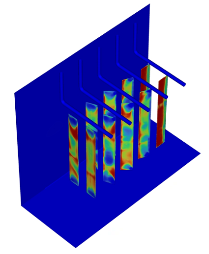
Ansys Fluent Dynamic Mesh Simulation Geometry
The geometry for this example simulation is a rectangular box which contains two rows of plate parts with five parts per row. The orientation of the parts is varied with respect to their y-axis. Hangars above the plate parts are also included. A symmetry plane is used at X=0.
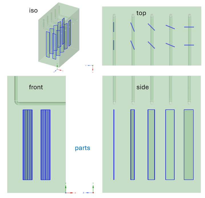
Named selections are recommended to label surfaces. Surfaces include the symmetry plane, extrusion mesh source surfaces, top free-slip surface, and the tank wall surfaces (side and bottom).
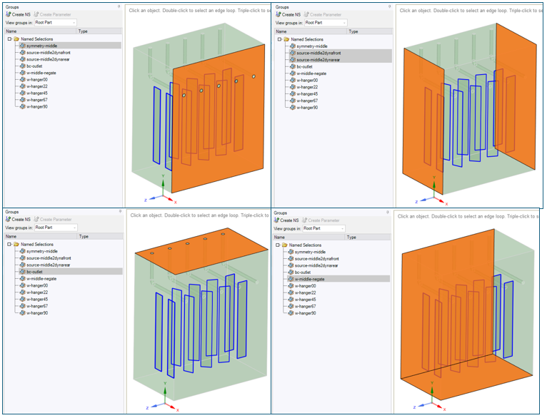
This geometry will be meshed with polyhedral mesh elements. Extruded mesh zones will be grown outward from the “source” surfaces.
Simulation Mesh
Fluent Mesh Mode is used to generate the volume mesh. The Watertight workflow is used. Geometry is imported using units of [mm], one face size Local Sizing of 2 [mm] is used for the plate parts, and the global min / max mesh sizes are 2 [mm] / 8.0 [mm], respectively. The geometry consists of both fluid and solid regions.
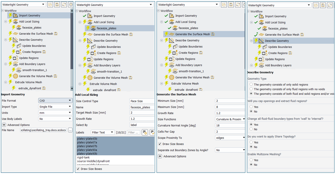
The top boundary is defined as a pressure-outlet, the source boundaries are defined as internal type, the symmetry boundary is defined as symmetry type, and the walls are retained as wall type. The plate part regions are all solid and the tank is a fluid region type. Five smooth-transition boundary layers are grown from walls of the fluid region.
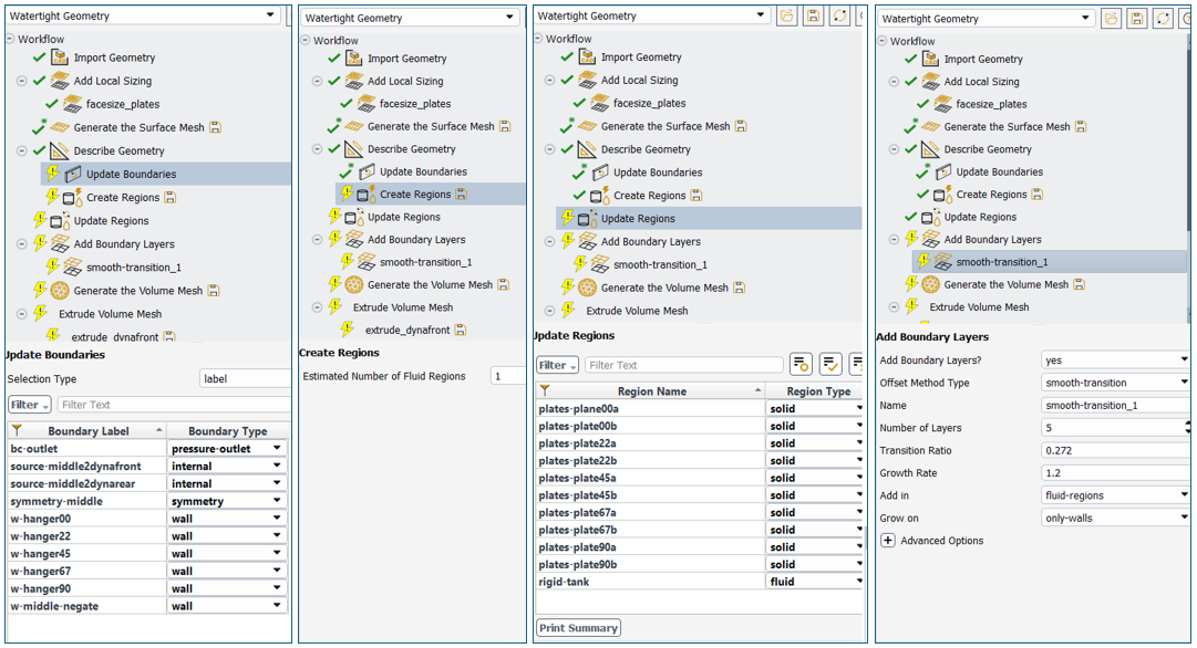
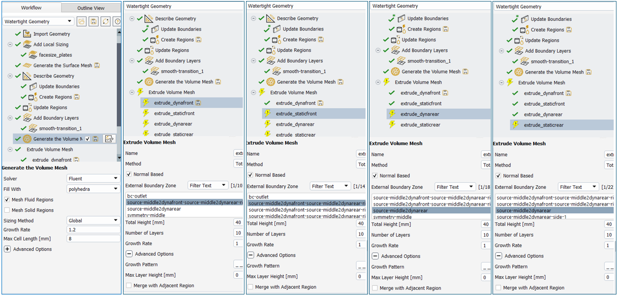
Polyhedral mesh elements fill the regions with a max size of 8.0 [mm]. Mesh Solid Regions option is DEACTIVATED. Four extrusions are then generated. Extrusion meshes are needed for the Fluent dynamic mesh to work properly. All extrusions use a growth rate of 1.0, all use a total height of 40 [mm], all use 10 layers, and all do not merge with adjacent region. Renaming the zone of each extrusion is recommended to find these zones readily in the solver mode.
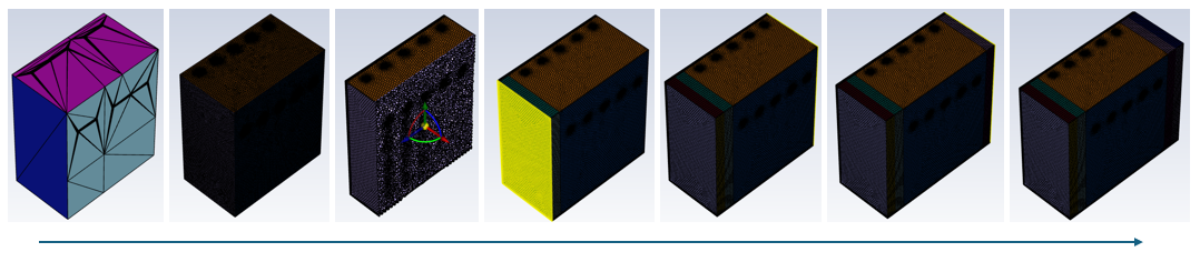
The progression of the mesh is shown below from import, through surface mesh generation, through polyhedral volume generation, and through extrusion mesh generation.
Ansys Fluent Dynamic Mesh Simulation Setup
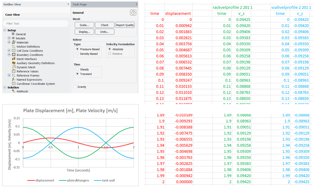
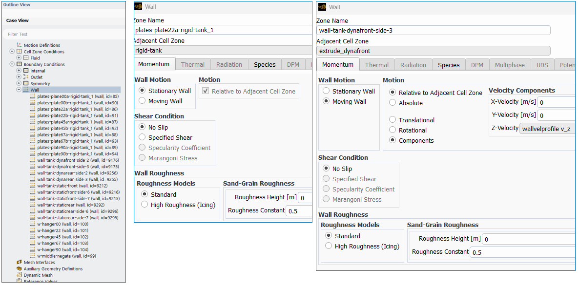
The simulation is transient. The middle three cell zones move in a sinusoidal fashion with a maximum displacement of 0.0295 [m], and the cycle period is 2 seconds. The velocity of the motion is obtained by taking the time derivative of the displacement. Transient table profiles can be generated from the velocity. The profile for rigid cell zone motion starts with a positive velocity in the Z-coordinate direction. A negative velocity profile is needed to impose a zero-velocity on the tank walls which do not move in reality. The profiles should be saved to a text file and read into Fluent solver as profiles with periodic flag activated. The header of the rigid motion profile could be “rackvelprofile 2 201 1”, and the header of tank wall profile could be “wallvelprofile 2 201 1”. The number 2 indicates the number of columns in the profile, the number 201 indicates the number of rows in the profile, and the number 1 indicates a periodic profile.
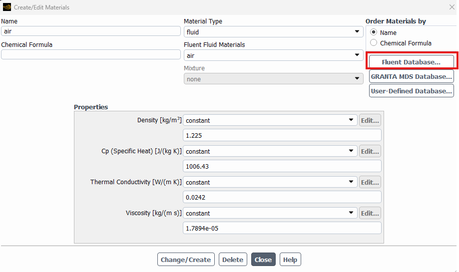
The simulation is single-phase and multiple-species. The mixture contains water and one tracer species. Both of the species have the properties of water. The mixture uses volume-weighted density, mass-weighted viscosity, and a constant (very low) mass diffusivity.
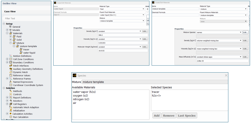
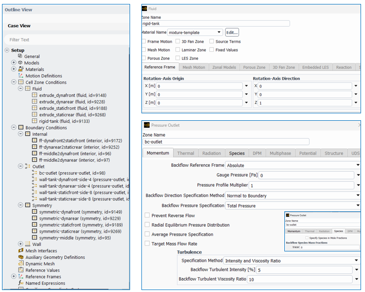
All the fluid cell zones use the mixture template for the material. Boundaries between fluid cell zones are specified as internal type. Boundaries along the symmetry plane are specified as symmetry type. All the top boundaries have a pressure outlet with zero mass fraction of tracer species.
All the walls have a “no slip” shear condition. Walls of cell zones that are moving with rigid motion have the wall velocity profile specified to negate the rigid motion to preserve stationary walls.
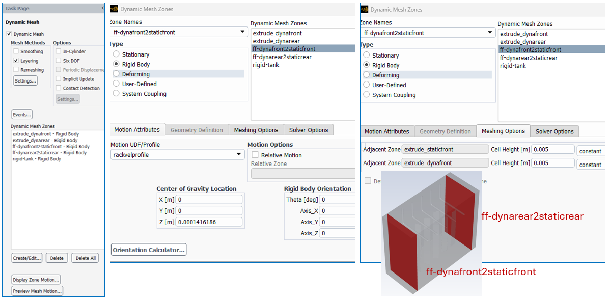
The dynamic mesh model is activated. All methods and options are deactivated except for Layering. A Rigid Body dynamic mesh zone is created for each of the middle three cell zones. The “rackvelprofile” is specified as the Motion Profile.
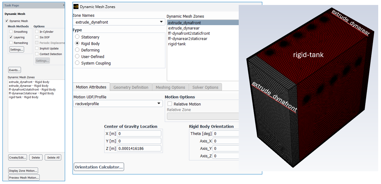
The boundary zones between the “dyna” and “static” cell zones also need to be specified as dynamic mesh zones. The same Motion Profile is specified. In addition, the cell height is set to 0.005 [m] in the Meshing Options tab. This size is consistent with the surface mesh size near those face zones.
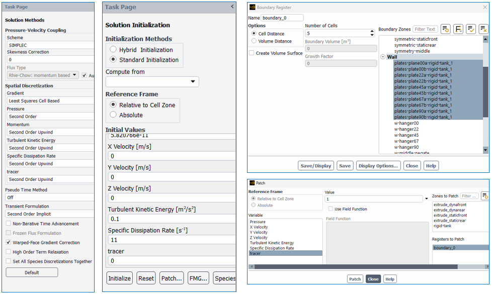
The domain should be initialized with zero mass fraction for the tracer. A boundary register should be created that specifies 5 cells from the plate walls. Then the mass fraction of tracer should be patched to 1 in this cell register. Second order implicit transient formulation is used. A time step size of 0.005 seconds is used.
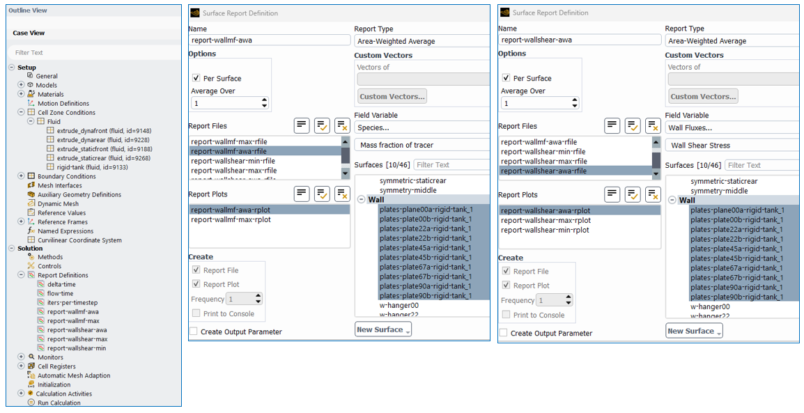
Report Definitions are generated to monitor the wall shear and the mass fraction of tracer on the plate surfaces. Report definitions such as area-average, maximum, and minimum wall shear and mass fraction of tracer are used for monitoring via files and plots.
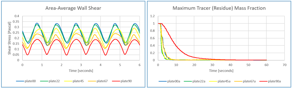
The wall shear plot below indicates different shear based on the time and orientation. The 90 degree orientation has the lowest wall shear which indicates poorer electroplating/coating/washing capability. The mass fraction plots show how tracer is washed away over time by the plate motion. The 90 degree orientation has the slowest removal rate of tracer over time.
Animated contour plots on the walls can show the mass fraction of tracer, the wall shear stress, and fluid/part velocity as the solution progresses.
Ansys Fluent Dynamic Mesh Simulation In Action
Mass Fraction of Tracer
Wall Shear Stress
Top View of Velocity Magnitude
Wall Velocity
Video Walk-Through of Ansys Fluent Dynamic Mesh Simulation Setup
The flowing video walks through the dynamic mesh simulation setup from the geometry to meshing to flow solver in Ansys Fluent.
SimuTech Group Can Help
Electroplating, coating, and washing systems must meet performance requirements across variations in part shape, orientation, and operating conditions. SimuTech Group’s Fluids team helps engineering organizations use Ansys Fluent Dynamic Mesh and other Ansys simulation tools to evaluate complex fluid behavior and make more confident design decisions earlier in development.
Whether you are working on an electroplating system, coating system, or washing system, SimuTech Group can help you develop robust CFD simulation workflows using Ansys Fluent Dynamic Mesh to evaluate moving components, transient flow behavior, and process performance.

Brian Peschke, Lead Engineer – Fluids
Brian Peschke is a mechanical engineer with more than 20 years of industrial experience specializing in computational fluid dynamics and the analysis of fluid and thermal performance. At SimuTech Group, he helps engineering teams apply CFD simulation to close knowledge gaps, troubleshoot complex performance challenges, and make more informed product-development decisions.