
 Contact Us
Introduction to Battery Cell Thermal Abuse Simulation
Battery cell thermal abuse can develop rapidly and behave differently depending on cell geometry, operating conditions, and the way an abuse event is initiated. Battery cell thermal abuse simulation in Ansys Fluent gives engineers a way to study these effects before relying on extensive physical testing.
In this Tips & Tricks guide, we look at cylindrical, pouch, and prismatic cell models and compare thermal-abuse scenarios including global overheating, localized heating, and nail penetration.
The Challenge of Thermal Runaway in Battery Design
Lithium-ion batteries are central to the electrification of vehicles and energy storage, but increasing energy density creates significant thermal-management and safety challenges. Under normal operation, heat generated within a cell must be removed efficiently to maintain an acceptable temperature and minimize temperature gradients. Under abusive conditions, however, localized heating can trigger exothermic reactions that accelerate the temperature rise and potentially lead to thermal runaway. Once initiated, thermal runaway can release a large amount of heat and may cause venting, fire, or propagation to neighboring cells. Predicting this behavior is challenging because it involves the interaction of electrochemical, thermal, material, and mechanical phenomena over different time and length scales. Cell geometry also has an important influence on thermal behavior. Cylindrical, pouch, and prismatic cells have different internal structures, surface areas, thermal paths, and packaging constraints. The way thermal runaway is initiated can also significantly affect the outcome. Uniform overheating, localized overheating, and nail penetration can produce very different temperature distributions and rates of heat generation. Experimental testing is essential, but testing every combination of cell design, operating condition, abuse scenario, and safety feature is costly and time-consuming. Engineers therefore need simulation tools that can help understand thermal runaway mechanisms and evaluate potential safety strategies before extensive physical testing.
Engineering Approaches to Mitigating Thermal Runaway
Battery safety is typically addressed using multiple layers of protection, beginning with prevention and extending to containment if thermal runaway occurs. During normal operation, battery thermal-management systems use air cooling, liquid cooling, conduction paths, heat spreaders, or combinations of these approaches to control cell temperature and minimize local hot spots. However, preventing thermal runaway entirely may not always be possible, making thermal propagation a critical design consideration. If one cell enters thermal runaway, the battery architecture should limit the heat transferred to neighboring cells and prevent a single-cell failure from becoming a larger system-level event. Potential solutions include thermal barriers, insulation, heat sinks, thermally conductive interface materials, increased cell spacing, and optimized cooling channels. These approaches involve important trade-offs. Highly conductive materials can improve heat removal during normal operation but may also provide an efficient path for heat from a failed cell to its neighbors. Conversely, thermal insulation can reduce propagation while making normal heat rejection more difficult. Cell format also influences the effectiveness of these solutions. Cylindrical, pouch, and prismatic cells provide different thermal paths and packaging constraints. Engineers must therefore evaluate mitigation strategies under representative failure conditions. Understanding how a design responds to different initiation mechanisms—including uniform internal overheating, localized overheating, and internal short circuits—is essential for developing effective and robust battery safety strategies.
Using Ansys Fluent to Evaluate Battery Safety Solutions
Ansys Fluent provides a computational framework for investigating battery thermal behavior and evaluating engineering solutions for thermal runaway. Fluent’s battery modeling capabilities can represent electrochemical and thermal behavior using approaches such as the Multi-Scale, Multi-Domain (MSMD) methodology, while thermal-abuse models can represent the heat generation associated with runaway reactions. This allows engineers to investigate how heat generation and heat transfer interact during an abuse event. A useful approach is to model a single cell and compare cylindrical, pouch, and prismatic geometries under several thermal-abuse scenarios. Uniform internal overheating can be represented as an elevated internal initial temperature to investigate the response to elevated cell temperature. Local overheating can be modeled using a localized heat source, allowing the development and propagation of hot spots to be studied. Nail penetration can be represented as an internal short-circuit event, producing localized heat generation within the cell. For each scenario, Fluent can provide detailed information about temperature distribution, peak temperature, heating rate, heat generation, and the progression of the thermal event. Engineering mitigation strategies can then be introduced into the model—for example, thermal barriers, heat sinks, modified cooling conditions, or changes to thermal interfaces—and their effectiveness can be quantified. This approach enables engineers to compare designs and understand the physical mechanisms behind improved thermal safety before committing to extensive experimental testing.
Simulation Results
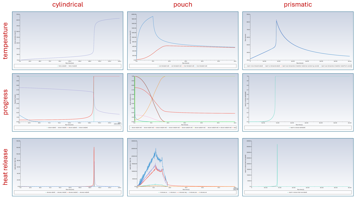
Key outputs from battery cell thermal abuse simulations include temperature, abuse reaction progress fraction, and abuse reaction heat release.
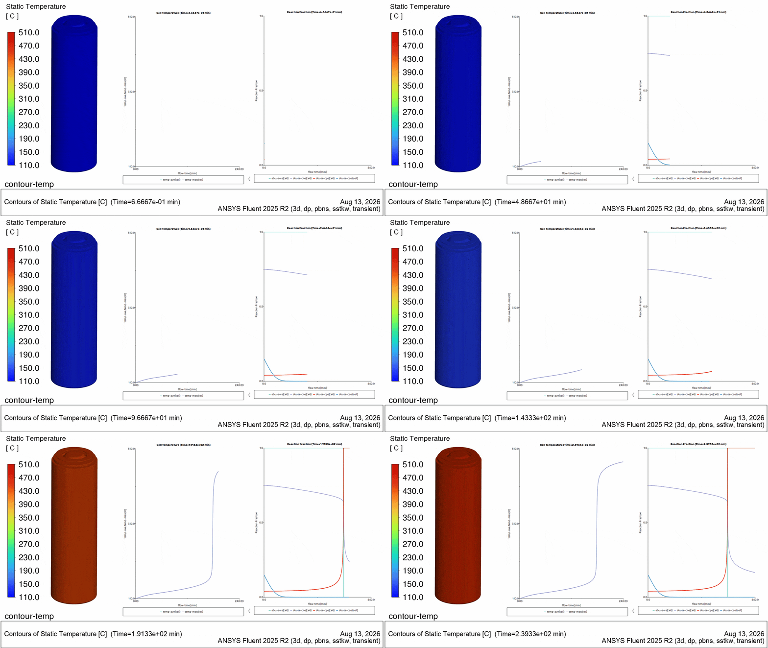
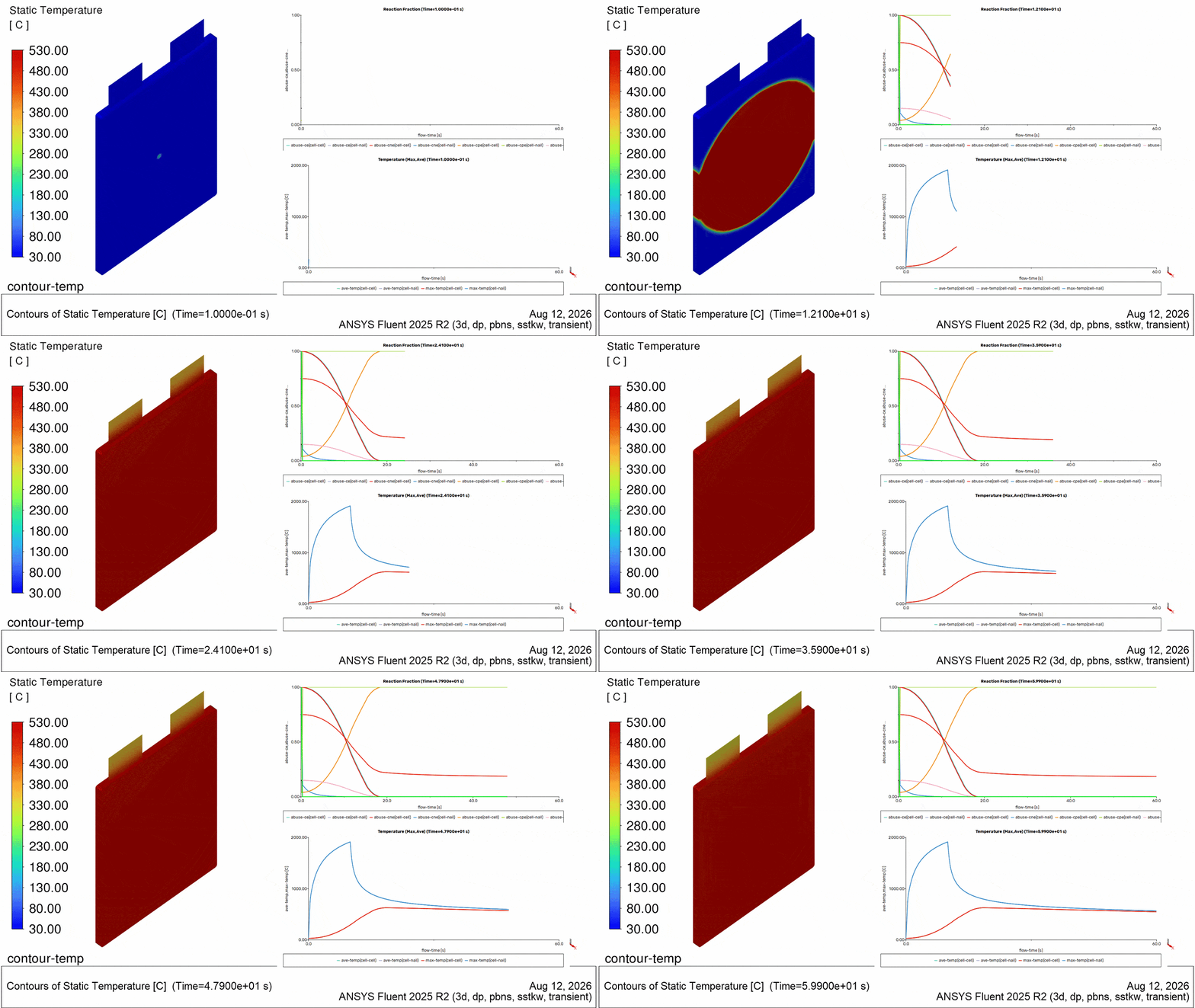
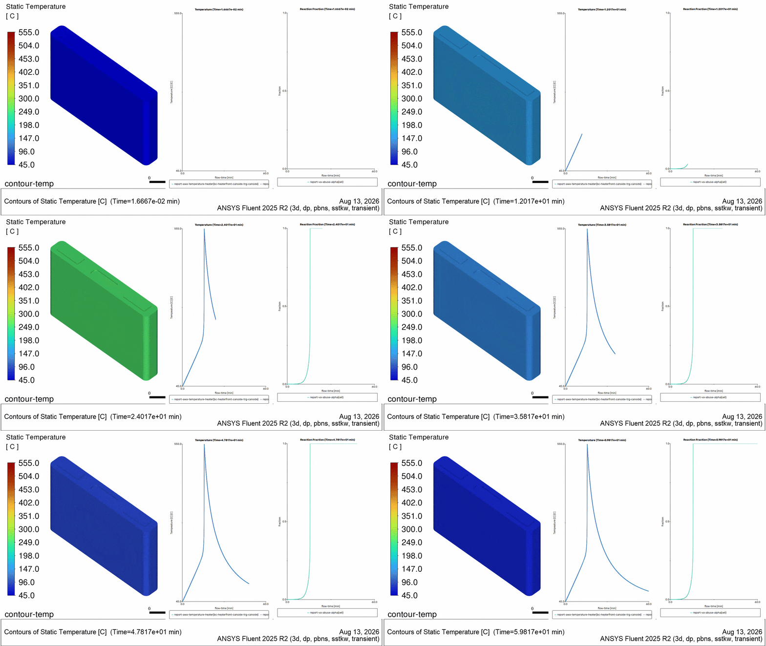
Below are animation results for 3 different scenarios. The contour plot shows the transient surface temperature of the battery cell. The embedded plots show the transient volume temperature and volume average reaction progress variables.
Cylindrical cell with global overheat: The battery is initialized at 110 [C], and the transient solution shows how the abuse exothermic reactions alone raise the cell temperature. Cell temperature slowly rises until heat release sharply rises and causes jump in temperature at about 178 minutes. The positive-solvent, the negative-solvent, and the electrolyte decomposition reaction experience large changes during this time and release large quantities of energy.
Pouch cell with nail penetration: Battery abuse is instigated by a concentrated heat source to represent nail penetration, and the transient solution shows how the abuse reactions propagate spatially through a cell. The nail zone temperature rises through the first 10 seconds, and this instigates abuse reactions in the neighboring cell. These reactions continue until the runaway is complete at about 18 seconds.
Prismatic cell with local overheat: Battery abuse is instigated by a diffuse heat source to represent two film heaters, and the transient solution shows how the abuse reactions propagate spatially through a cell. Temperatures slowly rise at the rate of 10 degrees C per minute until the abuse reactions accelerate at about 176 minutes and runaway begins. Temperatures spike and then drop as abuse energy is depleted.
Below are report monitors of the temperature, reaction progress fraction, and the abuse heat source for each geometry. They show the transient response and relationship between each metric. They also the relative reaction timing and heat release of the different 4-equation contributions.
Battery Cell Thermal Abuse Simulation Setup
Setup for this simulation with Fluent includes geometry preparation, meshing, and case setup.
Geometry
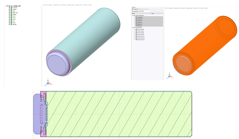
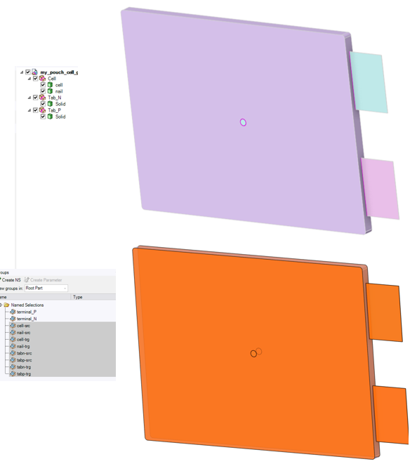
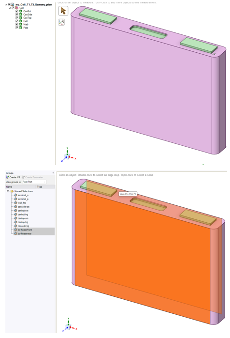
Simulation setup starts with geometry. The images below show three example geometries. They can be processed in Ansys SpaceClaim and Ansys Discovery.
Cylindrical Cell: The battery cell is 70 [mm] tall and 21 [mm] in diameter. Named selection groups are specified on the inner and outer shell surfaces for thin volume meshing.
Pouch Cell: The battery cell is 202 [mm] tall, 148 [mm] wide, and 7.5 [mm] thick. Tabs are included. Named selection groups are specified on the cell side surfaces for thin volume meshing.
Prismatic Cell: The battery cell is 108 [mm] tall, 164 [mm] wide, and 22.7 [mm] thick. Tabs are included. Named selection groups are specified on the shell-can inner and outer surfaces for thin volume meshing. Two additional named selection groups are used for the front and rear surface for purposes of overheating heaters.
Meshing
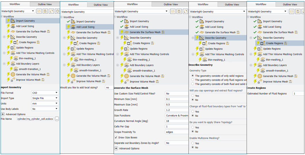
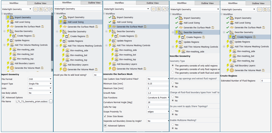
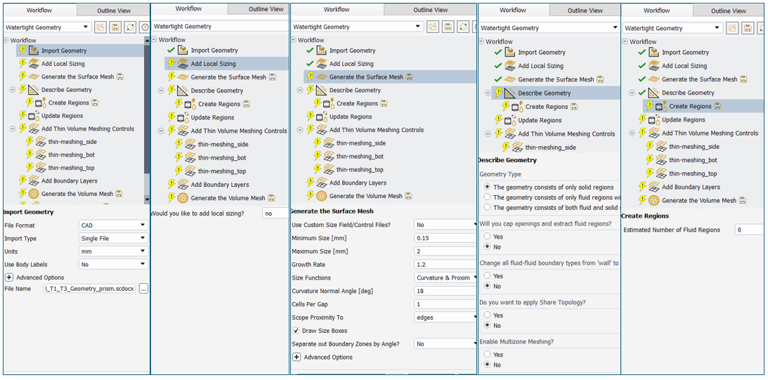
Meshing is accomplished using the Mesh Mode of Fluent with Watertight workflow.
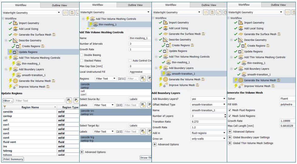
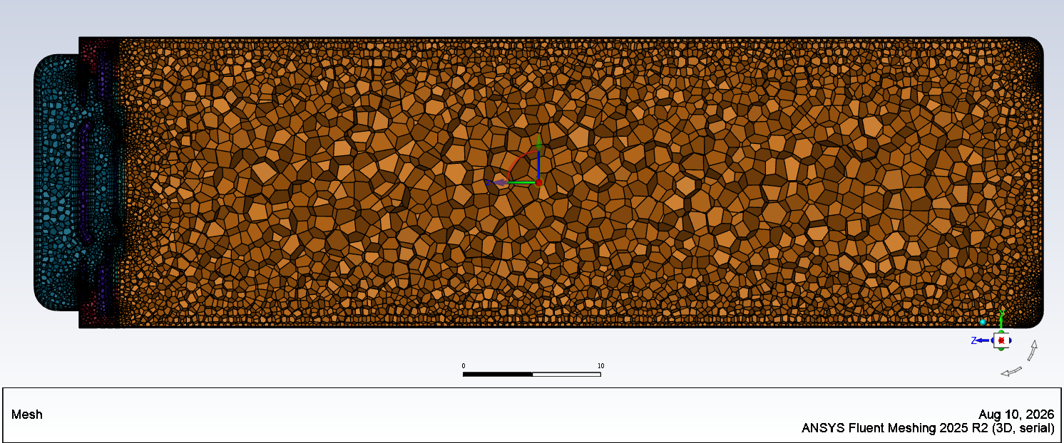
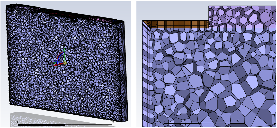
Cylindrical Cell: The global surface mesh size ranges from 0.1 to 0.5 [mm]. A fluid region can be specified at the top for venting simulation and include boundary layers. The shell-can volume is meshed with extruded cells via the thin volume meshing task. A polyhedral volume mesh is generated.
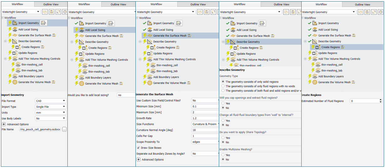
Pouch Cell: The global surface mesh size ranges from 0.1 to 2.0 [mm]. The cell and the tab volumes are meshed with extruded cells via the thin volume meshing task. A polyhedral volume mesh is generated.
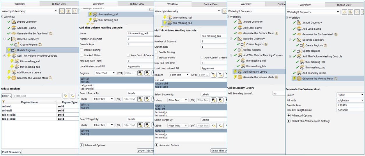
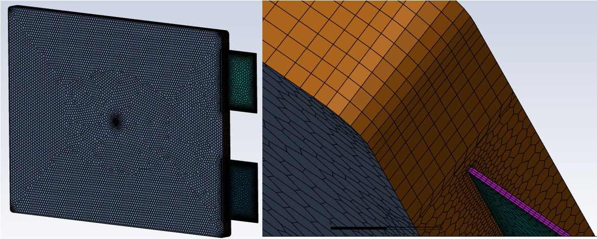
Prismatic Cell: The global surface mesh size ranges from 0.15 to 2.0 [mm]. The shell-can volumes are meshed with extruded cells via the thin volume meshing task. A polyhedral volume mesh is generated.
Solver Setup
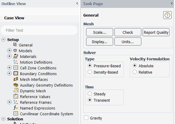
General Settings: All three models are transient in time and exclude gravity. Time and temperature units can vary from default.
| Cylindrical | Pouch | Prismatic | |
| Solver | Pressure-based | Pressure-based | Pressure-based |
| Time | Transient | Transient | Transient |
| Gravity | Off | Off | Off |
| Units | Minutes, Celsius | Seconds, Celsius | Minutes, Celsius |
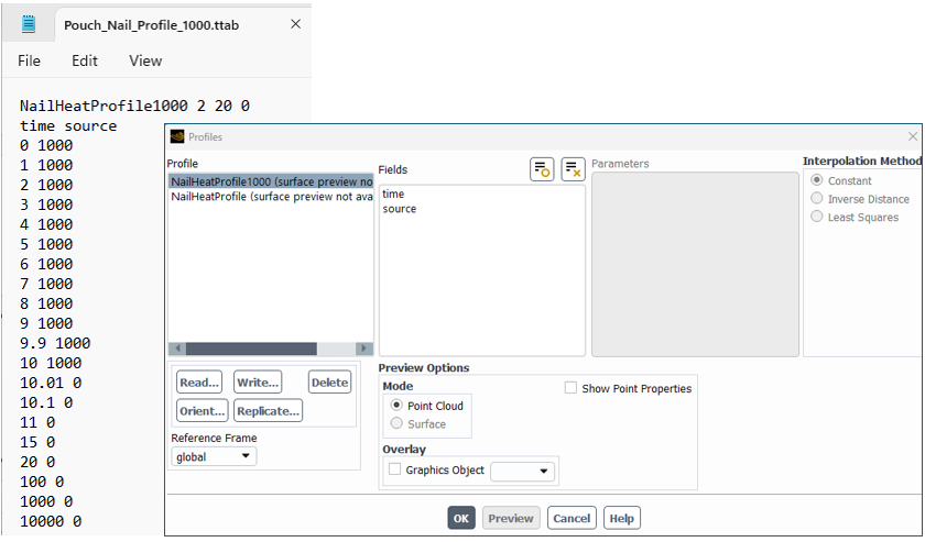
Profiles: A transient table is used to specify a volumetric heat release for the pouch nail, and a User Defined Function (UDF) is used to specify a volumetric heat release at the prismatic cell heater surfaces.
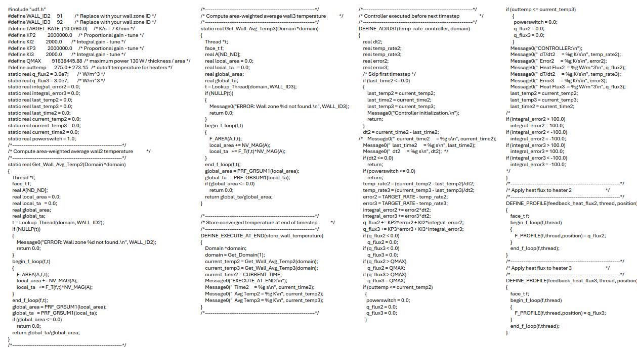
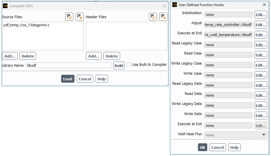
The prismatic scenario UDF calculates the average temperature at a heater face zone surface. It then calculates the volumetric heat generation needed to raise the temperature by a specified rate, such as 10 degrees Celsius per minute. As long as the heater temperatures are below a critical temperature, the UDF will attempt to increase the temperature at the specified rate with a maximum power of 150 Watts per heater. If the critical temperature is exceeded, then the heaters are deactivated. The UDF is compiled, and the Adjust and Execute-At-End functions are hooked.
| Cylindrical | Pouch | Prismatic | |
| Profile | None | Transient table | UDF |
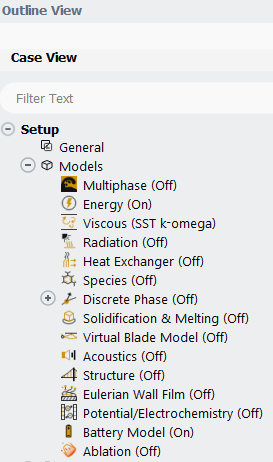
Physics Models: For this battery cell thermal abuse simulation example, the Energy equation and the Battery Model are activated.
| Cylindrical | Pouch | Prismatic | |
| Energy | On | On | On |
| Viscous | SST k-omega | SST k-omega | SST k-omega |
| Species Transport | Off | Off | Off |
| Battery | On | On | On |
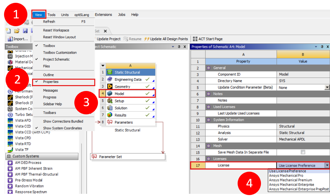
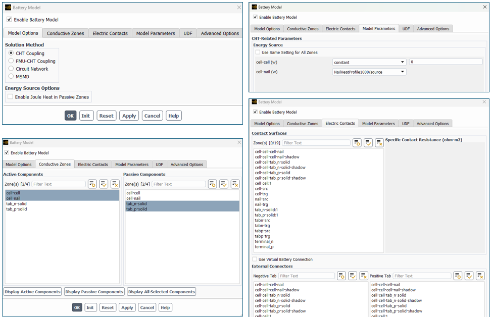
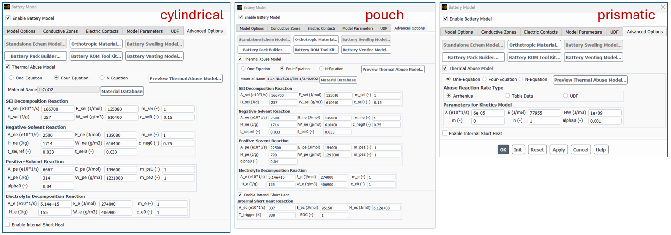
Battery Model: CHT-coupling is used, at least one active zone is specified, and the abuse model is activated. Default reaction kinetics inputs are used.
| Cylindrical | Pouch | Prismatic | |
| Method | CHT Coupling | CHT Coupling | CHT Coupling |
| Joule Heating | Off | Off | Off |
| Active cells | Cell | Cell, Nail | Cell |
| Passive cells | Tabs, Connectors | Tabs | Tabs |
| Electric Contacts | None | None | None |
| Model Parameters | 0 | Cell=0, nail profile | 0 |
| Abuse Model | Four-equation | Four-equation | One-equation |
| Material | LiCoO2 | Li1.1<Ni/3C1/32Mn1/32>0.9O2 | LiCoO2 |
| Internal Short | Off | On | Off |
| Venting Model | Off | Off | Off |
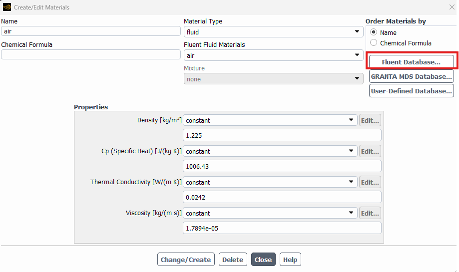
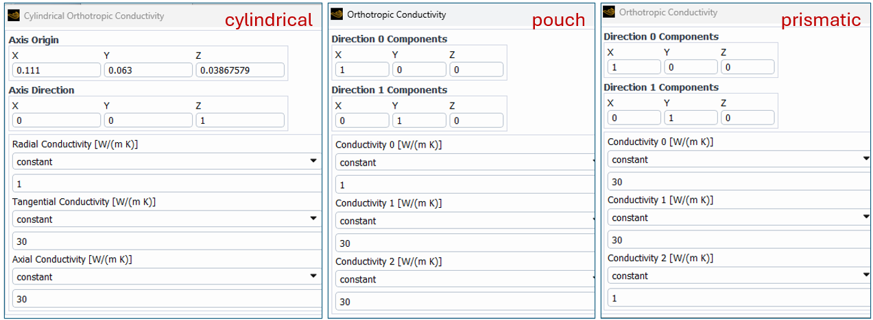
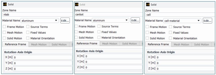
Materials: Cell material and aluminum are the primary materials in our battery cell thermal abuse simulation. Density, specific heat, and thermal conductivity are the primary properties. Properties are independent of temperature. Direction-dependent conductivity is used.
| Cylindrical | Pouch | Prismatic | |
| Cell density | 2789 | 3000 | 3000 |
| Cell specific heat | 1000 | 1224 | 1000 |
| Cell conductivity | Cyl-orthotropic | Orthotropic | Orthotropic |
| Al density | 2719 | 2719 | 2719 |
| Al specific heat | 871 | 871 | 871 |
| Al conductivity | 202.4 | 202.4 | 202.4 |
Cell Zones: Cell material and aluminum are assigned to cell zones.
| Cylindrical | Pouch | Prismatic | |
| Battery cell material | Cell material | Cell material | Cell material |
| Tabs material | Aluminum | Aluminum | Aluminum |
| Connector material | Aluminum | Aluminum | Aluminum |
| Shell material | Aluminum | Aluminum | Aluminum |
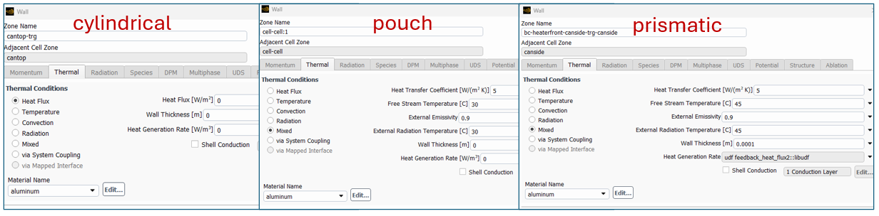
Face Zones: Internal walls in this battery cell thermal abuse simulation example are all specified with coupled thermal type boundary. External walls (walls with material only on one side) are specified with an adiabatic or a mixed thermal boundary condition type. The mixed thermal type requires a convective heat transfer coefficient, free stream temperature, surface emissivity, and external radiation temperature. The prismatic model also includes a volumetric heat generation at the heater face zones, and this requires a wall thickness value.
| Cylindrical | Pouch | Prismatic | |
| Internal walls | Coupled | Coupled | Coupled |
| External walls | Adiabatic | Mixed | Mixed |
| Mixed: HTC | 5 | 5 | |
| Mixed: Tfreestream | 30 | 45 | |
| Mixed: Emissivity | 0.9 | 0.9 | |
| Mixed: Tradiation | 30 | 45 | |
| Heater thickness | 0.0001 | ||
| Heater profile | UDF |
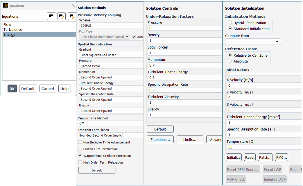
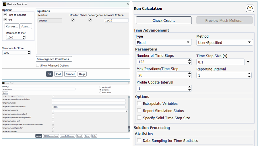
Solver Methods and Controls: Only energy equation is solved. Second order upwind spatial discretization is used for energy with an under-relaxation factor of 1.0. Energy residual convergence criterion is set to 1E-10. The bounded second order implicit transient formulation is used. The solutions are initialized with standard initialization, and time step sizes are specified. Secondary gradients are deactivated via (rpg) or with the TUI command: (rpsetvar ‘temperature/secondary-gradient? #f)
| Cylindrical | Pouch | Prismatic | |
| Equations | Energy only | Energy only | Energy only |
| Energy spatial | Second Order | Second Order | Second Order |
| Energy URF | 1.0 | 1.0 | 1.0 |
| Energy Criteria | 1E-10 | 1E-10 | 1E-10 |
| Time Formulation | Bounded 2nd Order | Bounded 2nd Order | Bounded 2nd Order |
| Initial temperature | 110 [C] | 30 [C] | 45 [C] |
| Time step size | 1 [sec] | 0.1 [sec] | 0.1 [sec] |
| Temp 2nd gradients | Off | Off | Off |
Report Definitions and Monitors: Report definitions are generated for our battery cell thermal abuse simulation to track output metrics such as temperature, reaction progress fraction, and reaction heat release. Heater temperature and heat release are also tracked for the prismatic scenario. Report types can include average, maximum, or integral. Battery output variables can vary based on which abuse model is selected (one- versus four-equation model). Report monitor files and plots are defined to use these report definitions.
| Cylindrical | Pouch | Prismatic | |
| Volume-average | SEI progress | SEI progress | Alpha |
| Volume-average | Pos solv progress | Pos solv progress | |
| Volume-average | Neg solv progress | Neg solv progress | |
| Volume-average | Electrolyte progress | Electrolyte progress | |
| Volume-average | Intrnl Short progress | ||
| Volume-average | Cell temperature | Cell, nail temp | Cell temperature |
| Volume-maximum | Cell temperature | Cell, nail temp | Cell temperature |
| Volume-integral | SEI Rx heat source | SEI Rx heat source | Abuse heat source |
| Volume-integral | Pos Rx heat source | ||
| Volume-integral | Neg Rx heat source | ||
| Volume-integral | Electrolyte heat src | ||
| Volume-integral | Intrnl Short heat src | ||
| Area-average | Heater temperature | ||
| Area Integral | Heater heat flux |
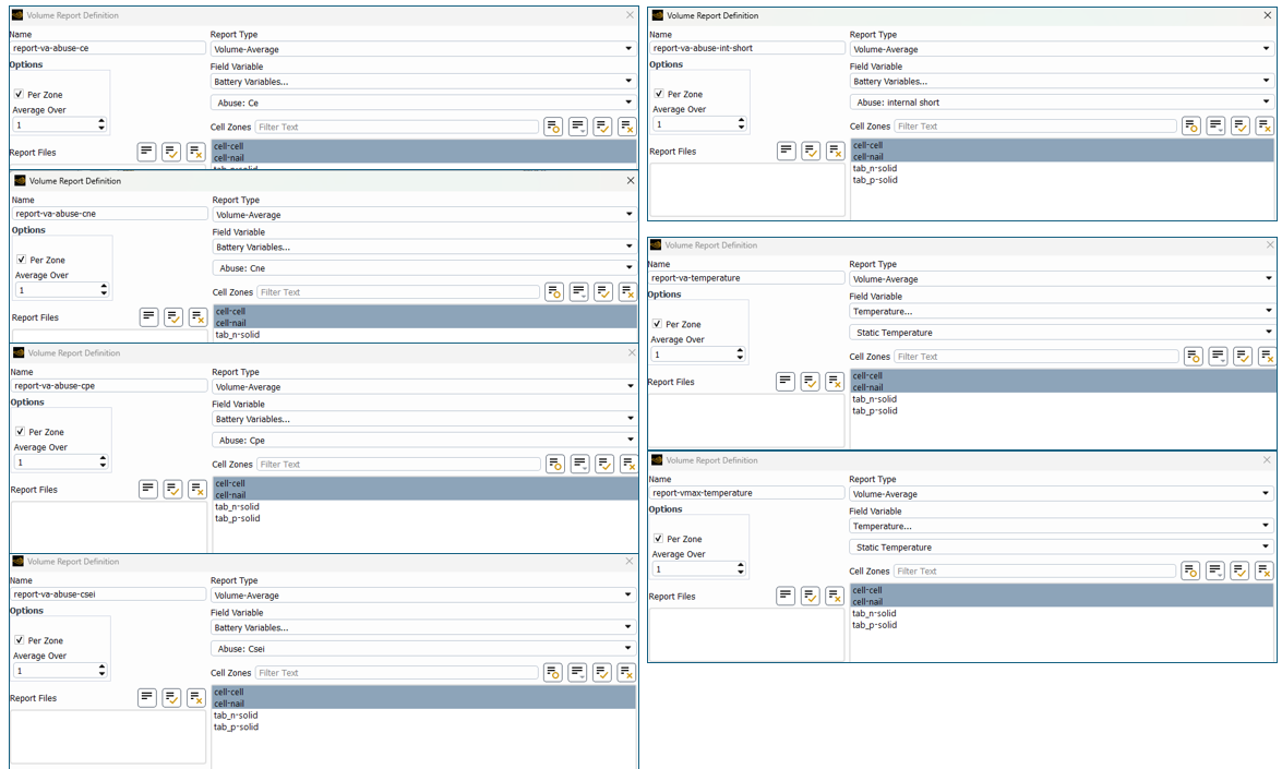
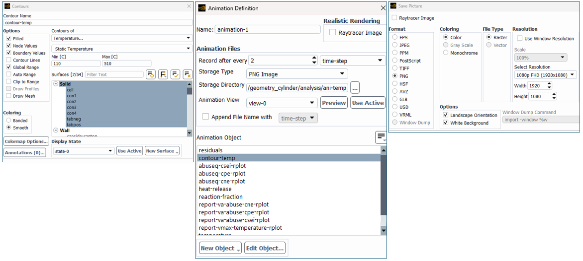
Graphics and Animations: Contour graphic objects of the part temperature can be generated to show both external and internal temperature of the battery. These graphic objects can be animated via solution animations. Monitor plots can also be embedded into the contour graphic object.
Video: Setting Up the Battery Cell Thermal Abuse Simulation Using Ansys Fluent
The following video walks through the simulation setups from geometry to meshing to flow solver.
Understand Battery Cell Thermal Runaway
Understanding thermal runaway at the individual battery cell level can improve product development progress prior to module-level development. Ansys Fluent can help engineers examine temperature rise, reaction progression, and heat release during battery abuse events while comparing different cell geometries and initiation methods. These simulations can also support evaluation of mitigation strategies such as cooling changes, thermal barriers, and other approaches designed to limit thermal runaway and propagation.
Need help with battery thermal simulation?
SimuTech Group can help you apply Ansys Fluent to battery thermal management, thermal abuse, and related CFD workflows.

Brian Peschke, Lead Engineer – Fluids
Brian Peschke is a mechanical engineer with more than 20 years of industrial experience specializing in computational fluid dynamics and the analysis of fluid and thermal performance. At SimuTech Group, he helps engineering teams apply CFD simulation to close knowledge gaps, troubleshoot complex performance challenges, and make more informed product-development decisions.