Introduction to Ansys Icepak Mesh Fusion Technology
This blog evaluates the Mesh Fusion technology available in Ansys Icepak to determine how it changes the generated mesh relative to the standard automatic meshing approach. The definition below, generated by AnsysGPT, provides the feature description used as context for this comparison:
The Mesh Fusion option in Ansys Icepak is designed to automate and optimize the meshing process for complex electronic designs. When enabled, Mesh Fusion automatically groups geometries within a mesh region and divides them into sub-domains, each of which is meshed separately using the most suitable meshing methods. This results in high-quality meshes and improved simulation accuracy for intricate assemblies such as PCBs and electronic components.
Key Features and Purpose
- Automated grouping and meshing: Mesh Fusion identifies and groups geometries within a mesh region, then partitions them into sub-domains for separate meshing.
- Optimized meshing methods: Each sub-domain is meshed using automatically selected techniques, tailored to the geometry’s characteristics, ensuring mesh quality and simulation fidelity.
- Flexible control: Mesh Fusion can be enabled or disabled globally (for the entire design) or locally (for individual mesh regions) via the Mesh Region dialog box.
- Improved mesh quality: By partitioning complex geometries and applying the best meshing strategies, Mesh Fusion helps achieve high-quality meshes, which are critical for accurate thermal and flow simulations.
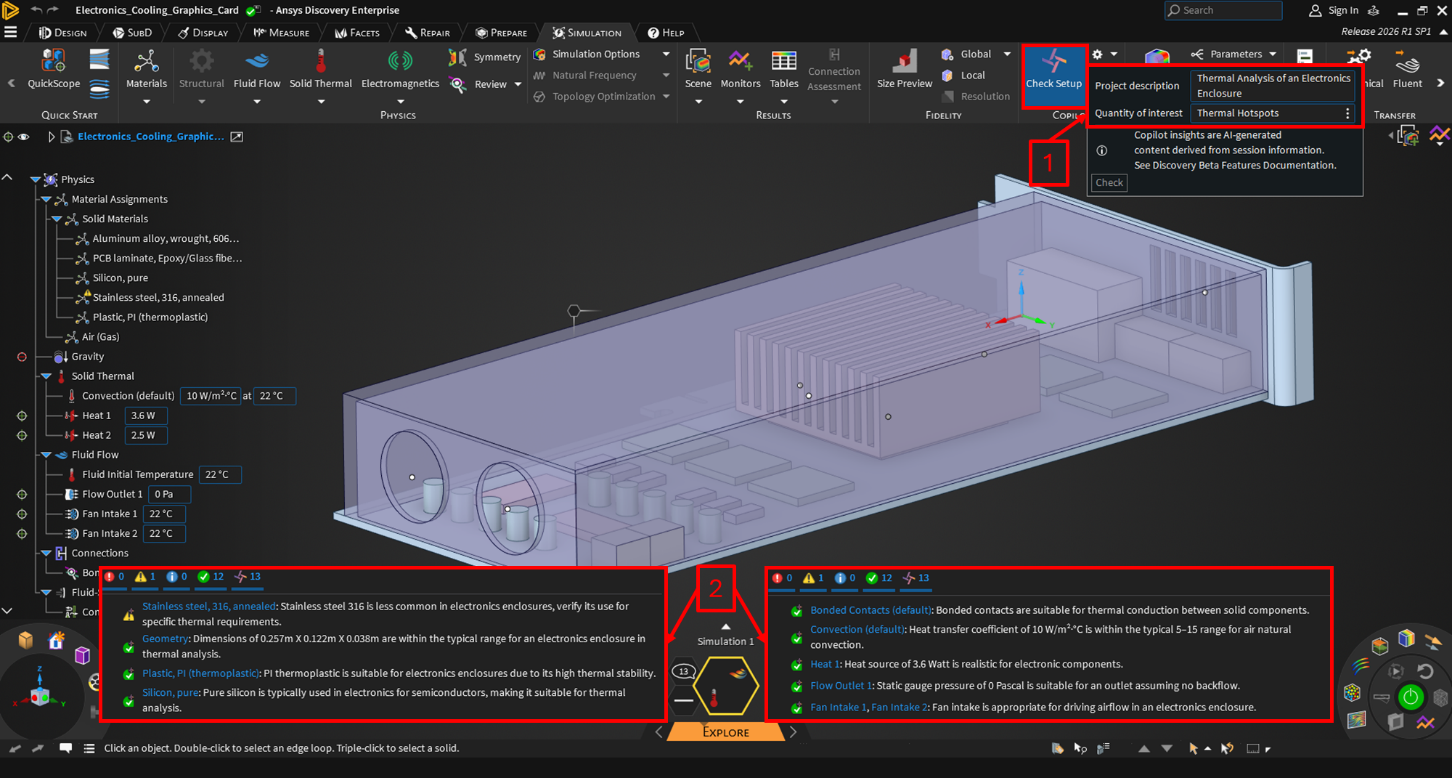
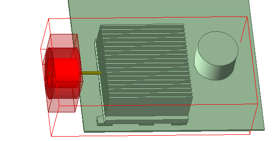
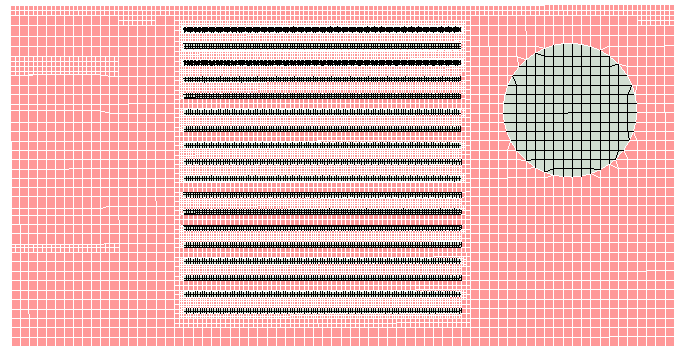
To evaluate this behavior, I created a simple electronics enclosure model with several heat sources, fans, a heat sink, and components with simple geometric shapes. The board is represented as a single solid block without detailed layers, traces, or vias. The model is shown below.
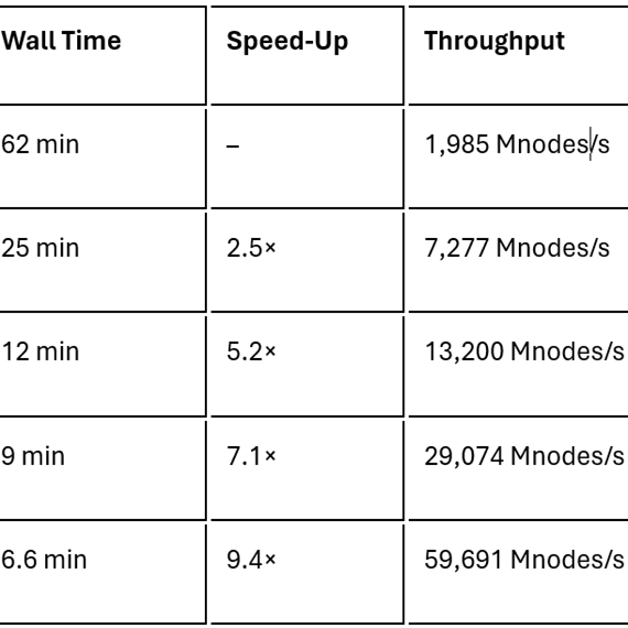
Four different meshes with and without Mesh Fusion option using global Level 4 and Level 5 slider bar method are generated. As shown in the table below, overall mesh quality remains broadly comparable across the cases.
| Mesh count | Face alignment | Skewness | |
| Slider bar level 4 | 342k | 0.464 | 0.031 |
| Slider bar level 5 | 768k | 0.361 | 0.039 |
| Mesh fusion level 4 | 218k | 0.342 | 0.075 |
| Mesh fusion level 5 | 1305k | 0.400 | 0.055 |
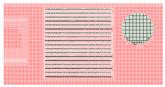
At level 4, the Mesh Fusion option produces only one fluid cell between the heat sink fins. Although this reduces the mesh count, the resulting resolution is inadequate. Figure 2 compares the resulting meshes on the same plane.
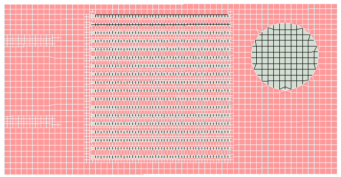
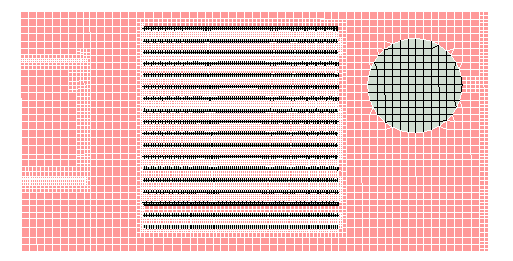
The comparison is then repeated at level 5 to evaluate the effect at a finer mesh setting. Figure 3 shows the corresponding mesh comparison. This time, Mesh Fusion option creates a higher count mesh. However, no significant resolution difference is observed in the two meshes in Figure 3.
The next step is to compare thermal results across all four different mesh configurations at the center plane.
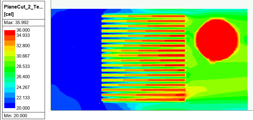
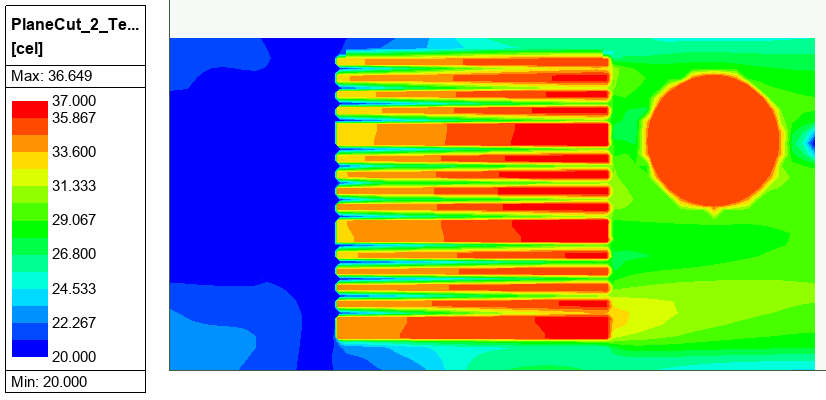
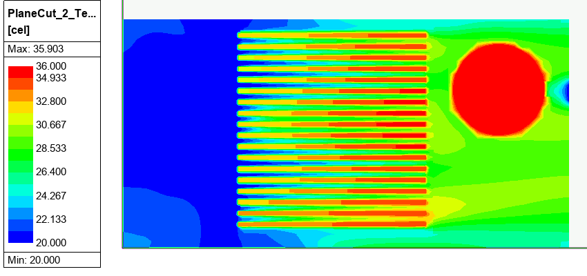
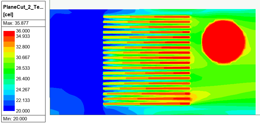
It is observed that at Level 4 with Mesh Fusion option, the poor resolution of air passages leads to overprediction of heat sink temperatures. The small cold air near the outlet is due to flow recirculation behind the circular part.
The next step is to compare flow speed across all four different mesh configurations at the center plane.
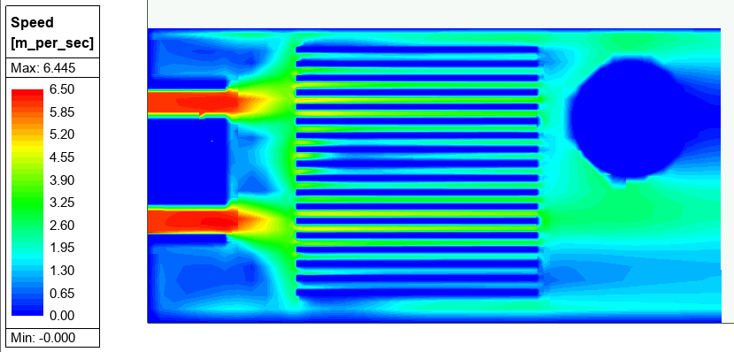
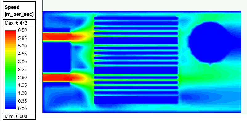
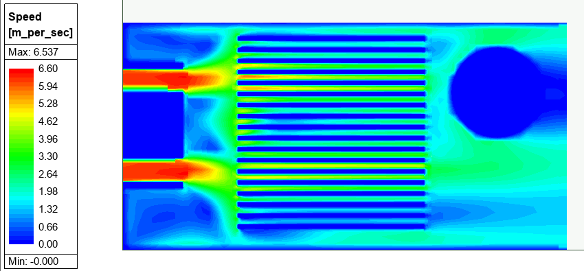
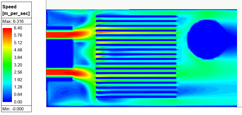
All models are predicting very similar air distribution except with Mesh Fusion Level 4 mesh that failed to resolve the air gap properly.
For this particular model, Mesh Fusion does not provide a clear advantage.
Need Help Optimizing Your Ansys Icepak Mesh Strategy?
Mesh settings can significantly affect electronics cooling results, especially when resolving heat sink fins, airflow paths, and thermal gradients. If you’re unsure whether Mesh Fusion, slider-bar meshing, local refinement, or another Ansys Icepak meshing approach is right for your model, SimuTech Group can help you evaluate the best path forward.

Mert Berkman, PhD Aerospace Engineering
Lead Engineer – Fluids, SimuTech Group
Mert Berkman is an aerospace engineer with a PhD in Aerospace Engineering and extensive experience in computational fluid dynamics, combustion, thermal-fluid analysis, and advanced engineering simulation. At SimuTech Group, he supports customers across complex fluids applications, helping engineering teams model challenging flow behavior, evaluate thermal and combustion performance, and apply simulation more effectively to real-world design decisions. His background spans aerospace research, automotive systems, power generation, turbomachinery, and technical consulting, giving him a broad perspective on how CFD can be used to understand performance, improve reliability, and reduce development risk across highly engineered systems.