Why Conducted Emission Simulation Matters for EVs
The increasing complexity of today’s wireless RF devices increases the demand for accurate and efficient simulations of large, complex RF designs. Identifying and predicting potential issues early in the design process saves resources, time, and money. As performance requirements increase and electronics proliferate, the risk of interference leading to degraded performance, unintended consequences, or even failure rises dramatically. Meeting electromagnetic compatibility (EMC) and regulatory standards, for example, CISPR 25, is highly important in the electric vehicle industry. Using Ansys HFSS combined with the Ansys Circuit tool, the full electrical system can be simulated to identify and mitigate potential EMI/EMC issues, reducing physical testing and delivering high-performance, safe, and compliant designs.
Overview
In this blog, we will use Ansys Electronics Desktop (AEDT) to run a conducted emission analysis of a full-electric vehicle, including the chassis, battery, cables, inverter, motor, and antenna, as shown below.
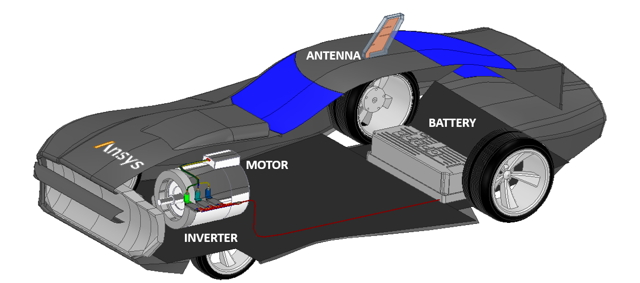
Ansys HFSS will be used to simulate the full vehicle, and Ansys Circuit will be used to perform transient analysis to calculate the conducted emission of the full system.
HFSS Model Setup
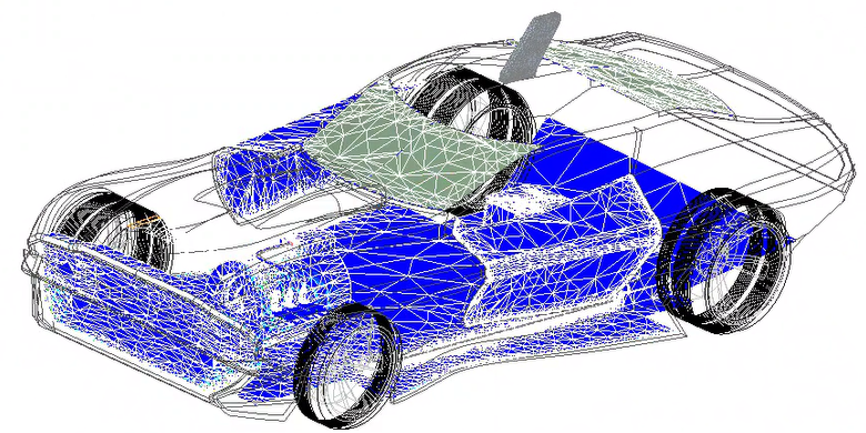
In this demo, we will simulate the vehicle model with HFSS. The HFSS model will be simulated at 100 MHz, with a frequency sweep from DC to 100 MHz using 401 points. The simulation takes 1 hour and 56 minutes to solve on a 24-core machine with a RAM requirement of ~76 GB. The figure shows the adaptive mesh generated by HFSS.
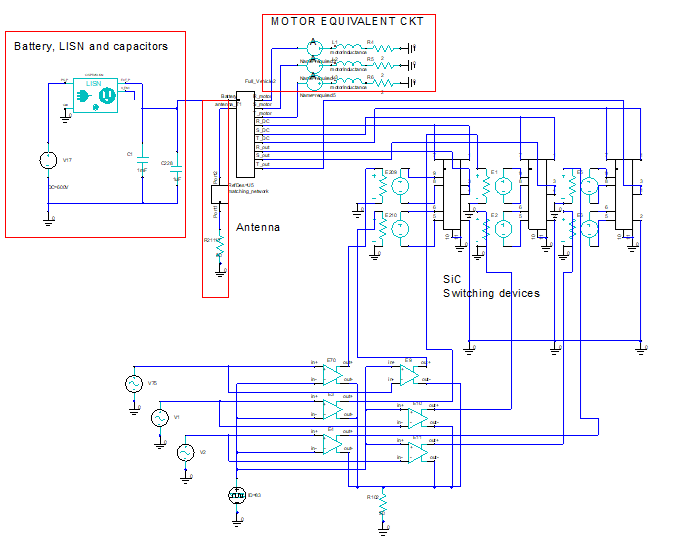
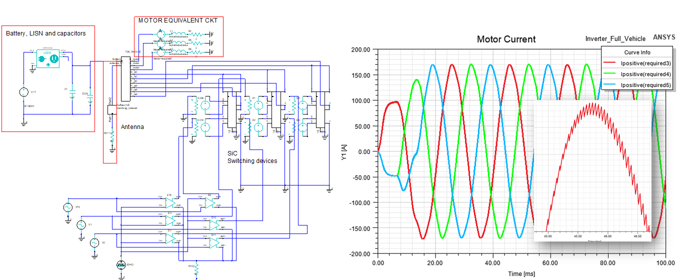
Full Circuit Model
After the HFSS simulation is completed, we can drag and drop the HFSS model into the circuit. The HFSS model will be linked as an S-parameter block. Below is the circuit model, including the details of the whole system. The LISN component selected for this example uses the CISPR25 standards.
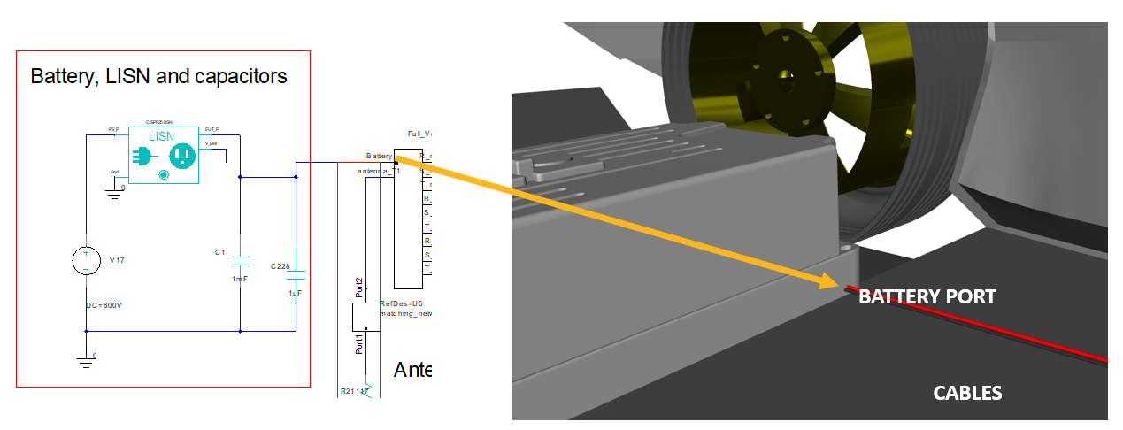
Battery
A 600 VDC battery is connected to the LISN for CE simulation, and two capacitors are added to suppress some of the noise. Cables connect the battery to the busbar, as seen below.
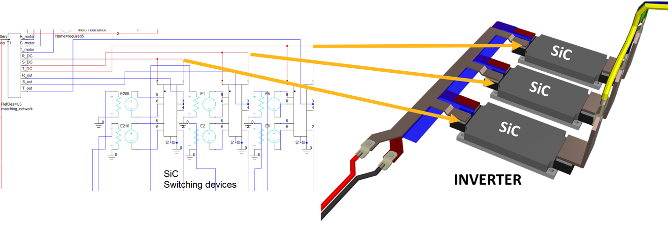
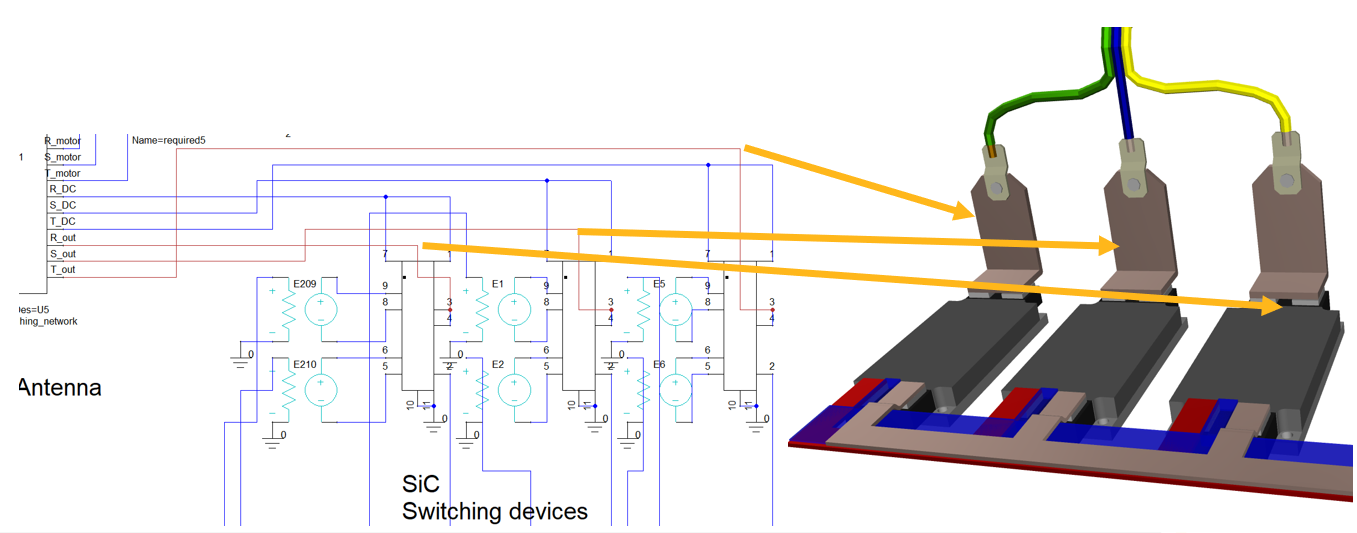
Inverter
The 600 VDC from the battery is connected to the busbar and powers the 3 SiC FET inverter. The SiC switching FET outputs the signal to the three terminals that are connected to cables that lead to the motor, as illustrated in the figures below.
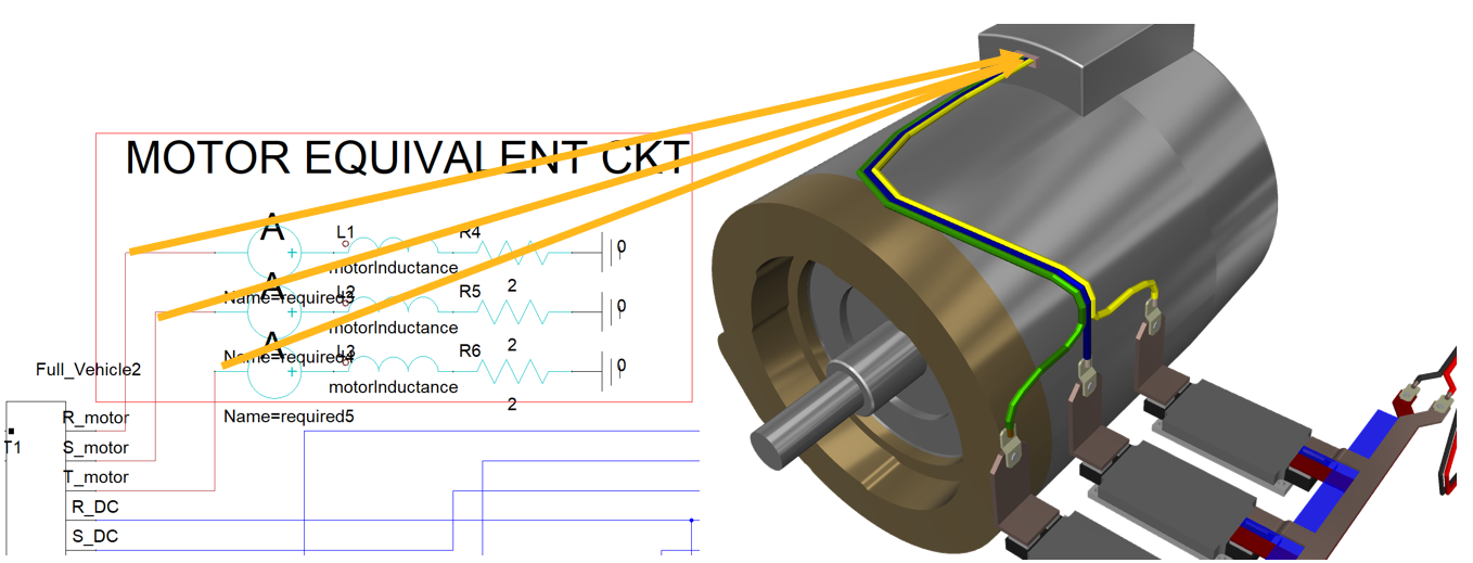
Motor
The motor is represented in a circuit with an equivalent circuit representation and is connected through cables.
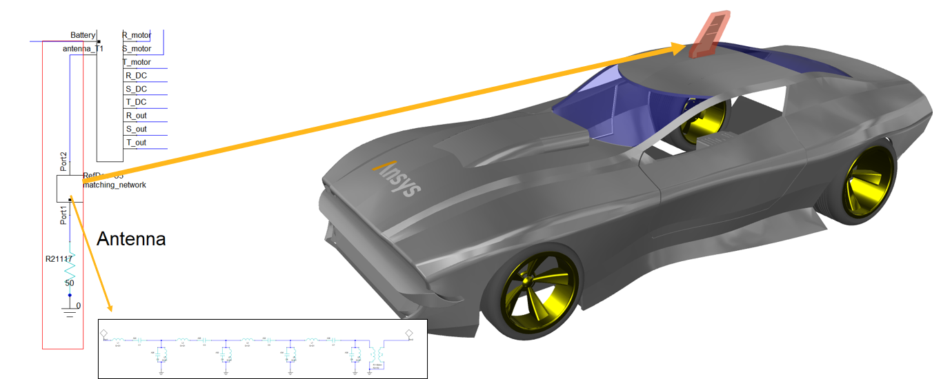
Antenna
The model also has an antenna placed on the car roof. The antenna is connected to a matching network in a circuit to improve the matching as seen below, and is terminated with a 50 ohm resistor in the circuit model.
Simulation Results
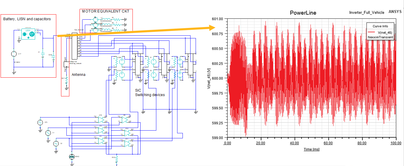
LISN Output Voltage
The figure below shows the power line voltage versus time at the LISN output.
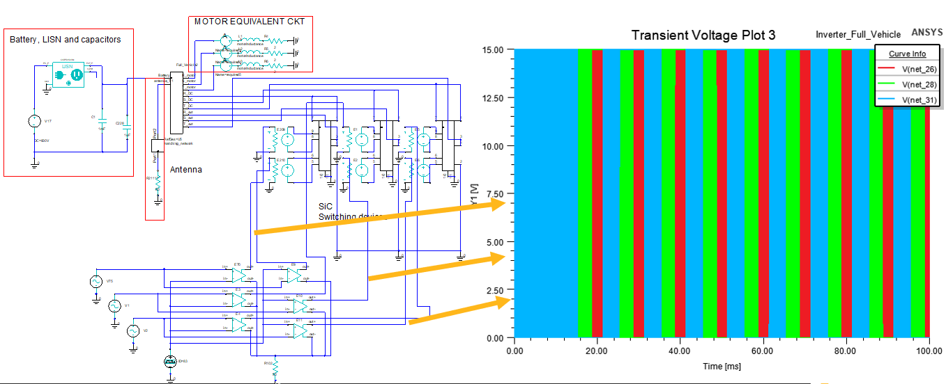
Switching Waveform
We can also plot the switching waveform as shown below.
Motor Current
The circuit simulation also calculates the current versus time at each node in the circuit. For example, we can plot the motor current as shown below.
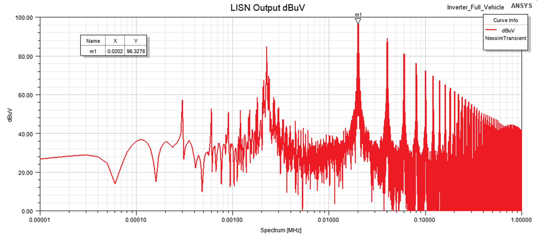
Conducted Emission Spectrum (FFT)
In circuit post-processing, we can also use the built-in FFT algorithm to calculate the spectral response of the transient simulation results. In the figure below, we show the conducted emission in dBuV at the LISN output.
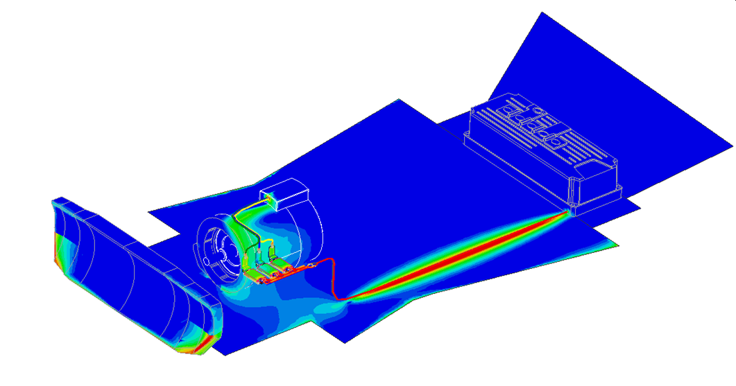
Pushing Excitations Back to HFSS
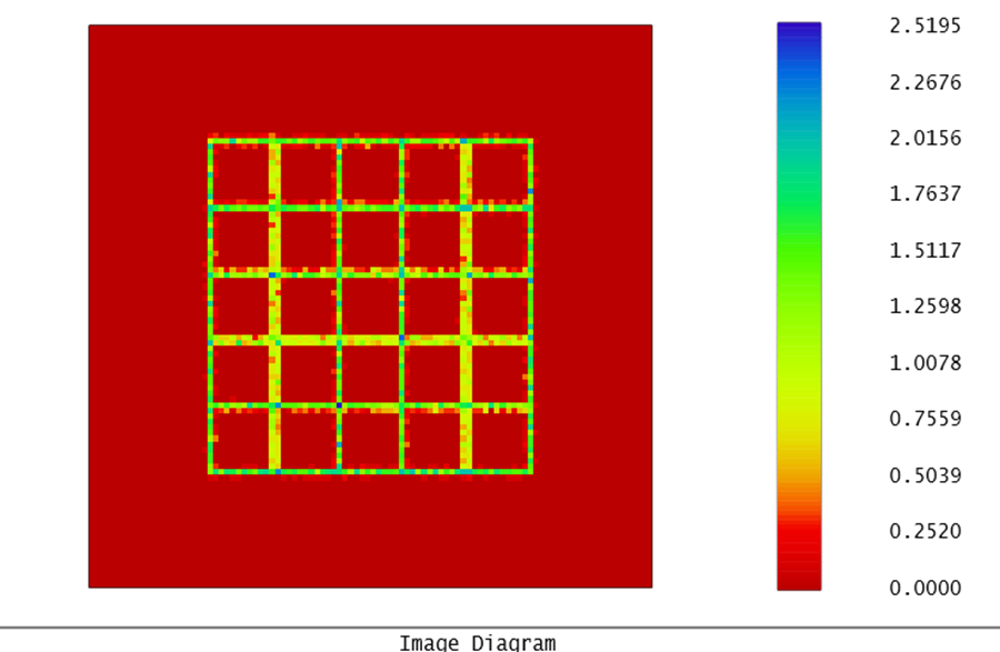
After the circuit simulation is completed, we can push the calculated excitations back into HFSS to adjust the excitation magnitude and phase, and update the fields plot as a post-processing step, without the need to re-resolve the HFSS model. Below, we see the updated magnetic fields plot at 20 KHz after pushing the excitation.
Video Demonstration
A complete demonstration is provided in the video link below:
Downloadable Resources
Electric Vehicle Model
Working on EMI/EMC simulation for electric vehicles or complex RF systems? SimuTech Group’s EMI/EMC consulting engineers can help you evaluate conducted and radiated emissions using Ansys HFSS and Circuit. For more on HFSS antenna and platform capabilities, see our webinar on antenna platform integration with Ansys HFSS. Contact us to discuss your EMC simulation needs.