Contact Us
Introduction to Ansys Mechanical Pull Tool
In this blog entry, we will explore one of the lesser-known mesh editing tools available in Mechanical: the Pull tool. Although it offers several capabilities, we will focus primarily on the Extrude options and work through a series of practical examples to better understand how the tool behaves under different conditions.
The Pull tool can be used to generate solid meshes from existing shell or surface meshes, create structured hexahedral-like meshes, define custom extrusion directions, follow complex target geometries, and even generate shell coatings on solid bodies. Through these examples, we will see how mesh density, extrusion direction, target geometry, and layer definitions influence the final mesh quality and shape.
Whether you are looking for a quick way to create layered solid meshes, simplify the meshing of thin-walled structures, or experiment with mesh-based geometry creation, the Pull tool provides several useful capabilities that are often overlooked.
Ansys Mechanical Pull Tool In Action
First of all, some basic concepts.
Pull enables you to extrude or revolve element faces, to generate solid mesh. Pull generates volume of solid elements for the specified height or revolved volume from the source mesh along the specified coordinated system or the face normal vector. Pull allows you to create surface coating on solid bodies to generate shell mesh.
Each connected set of elements forms a body. Each body has a top, bottom and side face. And edges are created bounding the top and bottom face. When you Extrude or Revolve object from CAD topology, bodies of the Pull part match the bodies of the base mesh. Bottom faces of the pull bodies match those of base mesh and top face match the corresponding face of the base mesh. A side face is created for each edge of the CAD topology. Edges and vertices of Pull bodies are created to form watertight solids.
Extrude
First Example: The Simplest Extrusion
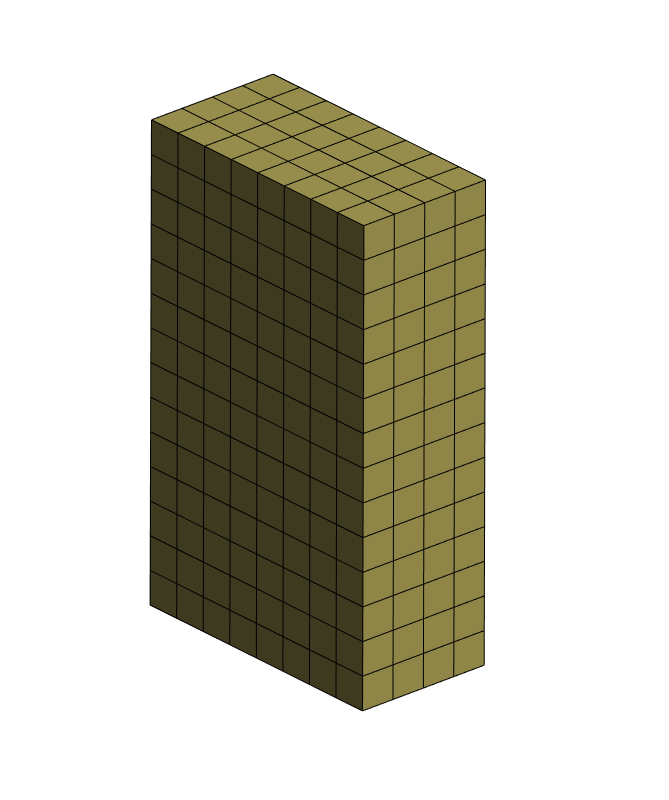
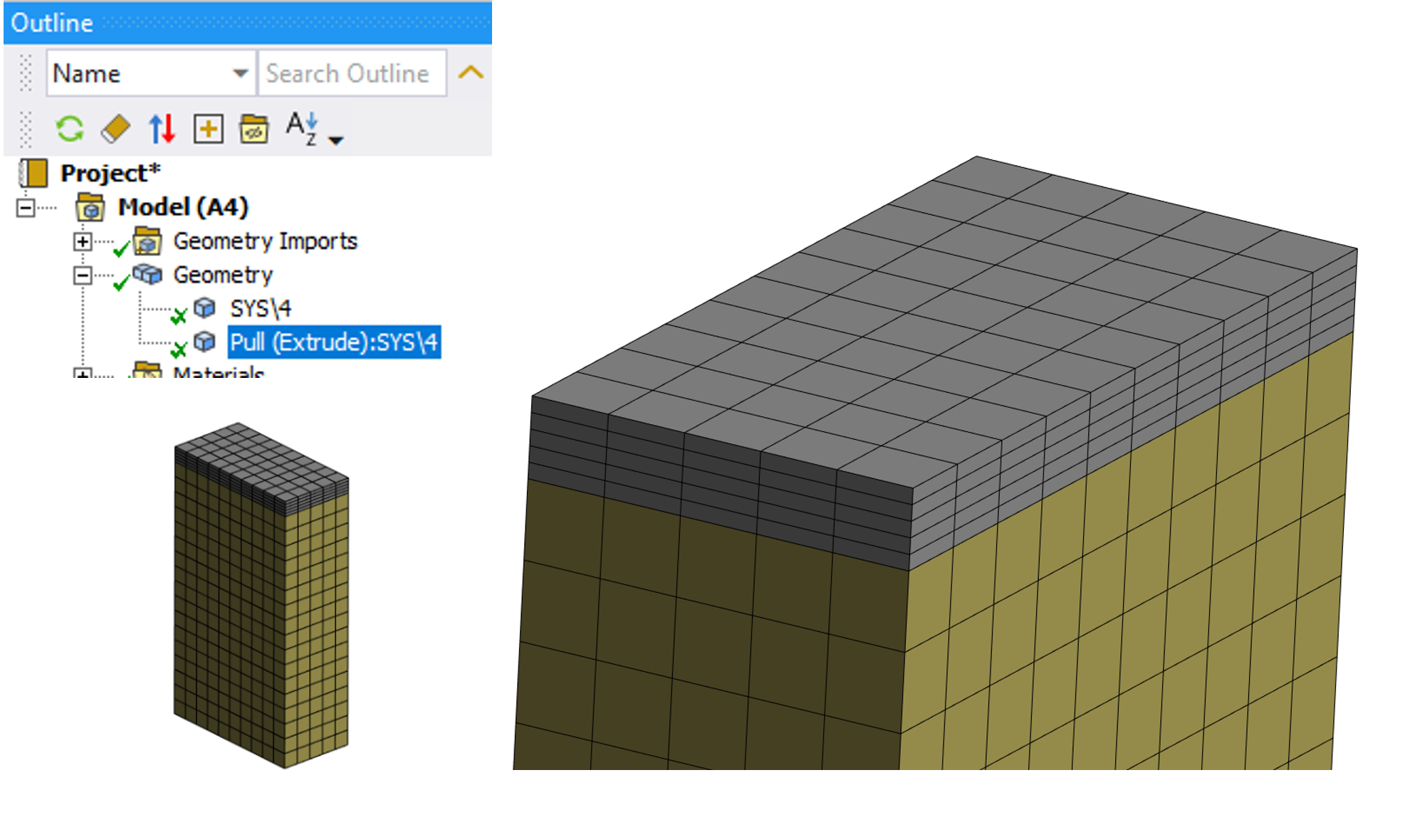
For this case, we want to create new elements over the top surface of the base shown model. It needs to start with a base mesh. If the base body is not meshed, it will be meshed before executing the extrude operation. Remember this is a Mesh Edit tool.
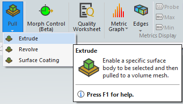
To access the Pull tool, you can use the Mesh Context Menu → Mesh Edit → Pull
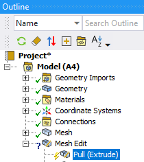
Then, the Mesh Edit object will be created in the tree with the Pull child object on it.
We populate the scope with elements, element faces, geometric faces or sheet bodies. For this example, the top face.
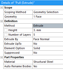
Then, it is necessary to define the total Height (3 mm) and Number of layers (5). All remaining fields can be left by default. The result is a new body with five layers of elements spanning a total thickness of 3 mm on the top of the original body. Note the mesh pattern is equal to the base body top mesh faces and the extrusion direction is normal to the base face. This allows the new body to have a nice hexahedral mesh. Spoiler Alert! This is a powerful way to reduce effort in creating this mesh type.
Second Example: UpTo and Offset Geometry
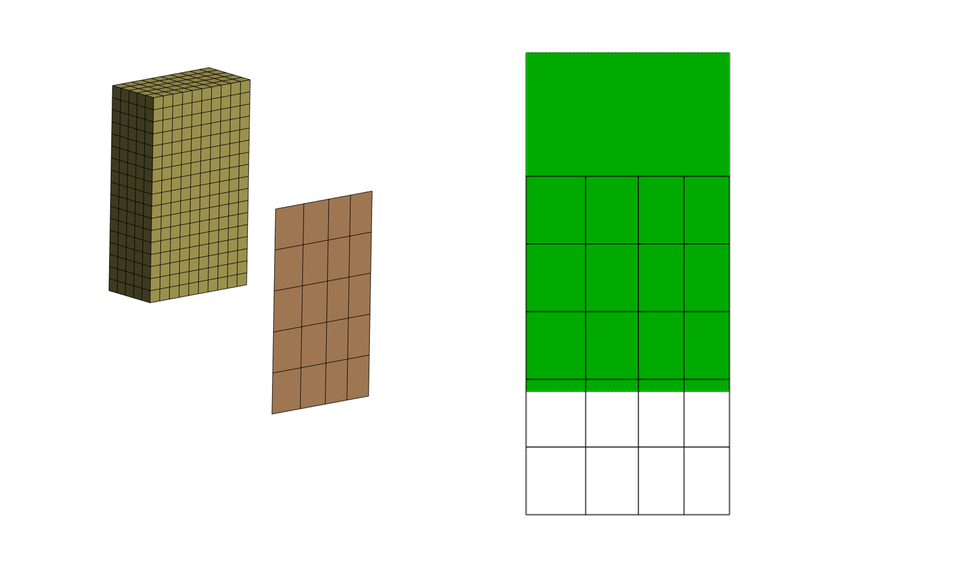
For a more complex example, we want to define the height of the extrusion by selecting an independent surface which is a lateral face of the 3D body. There are dissimilar meshes and the base face is the shell coarse mesh. Additionally, the base surface is not aligned with the UpTo face as shown. Note one and a portion of the lower rows fall outside the UpTo face.
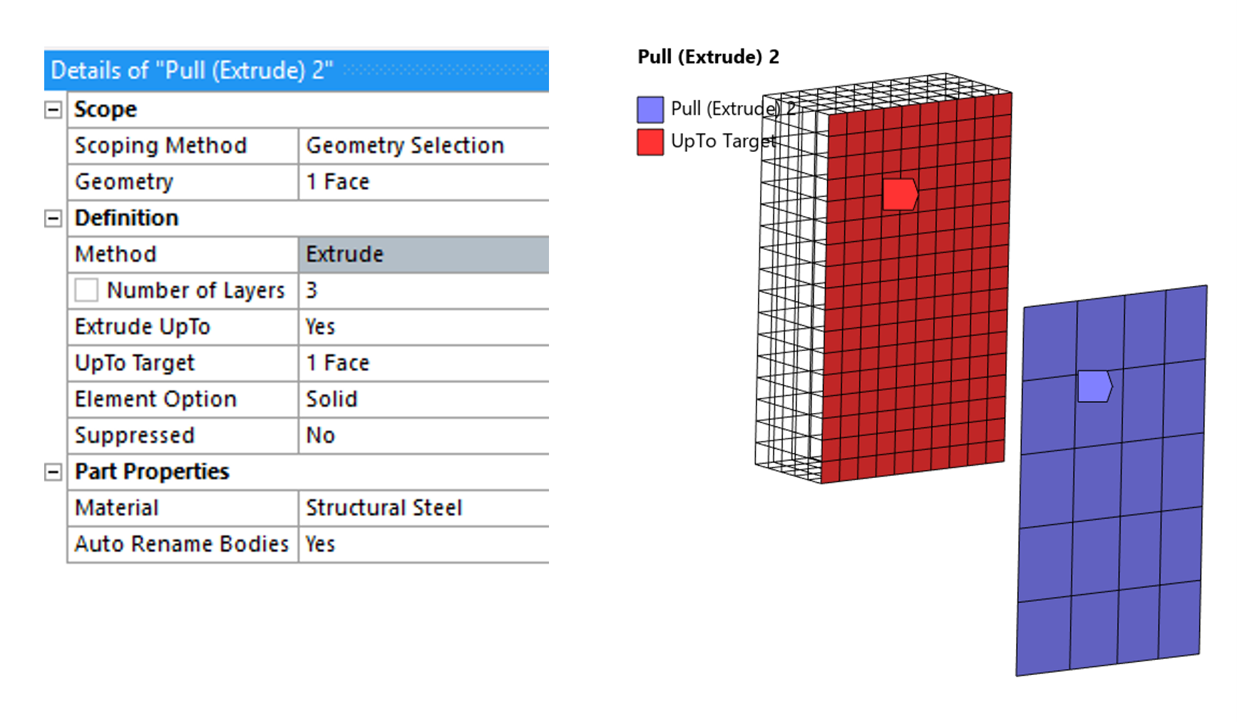
The Pull object needs to be defined by ‘Extrude UpTo’ as ‘Yes’ and then selecting the desired Face. 3 layers were defined to fill the gap between the shell elements and the UpTo face. Here the shell thickness property has no effect on the final body.
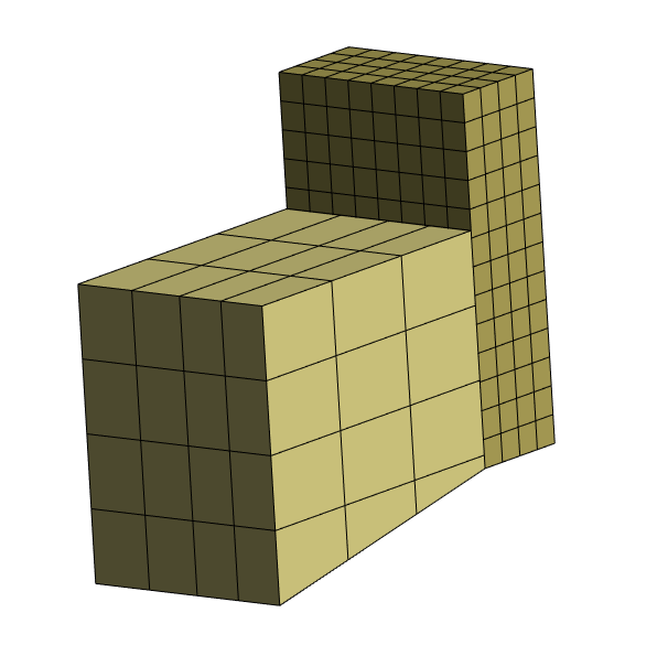
As result we have this new body. One important aspect to note is that the extruded body cannot lay outside the UpTo surface, the last row has been removed and the partially covered row has been tapered to fit the UpTo face bottom boundary line. Another important aspect is that the mesh density of the base face will affect the final quality of this last row.
Third Example: Normal Direction Using Full Body
We can also use this technique to facilitate 3D Mesh in thin wall complex bodies when needed.
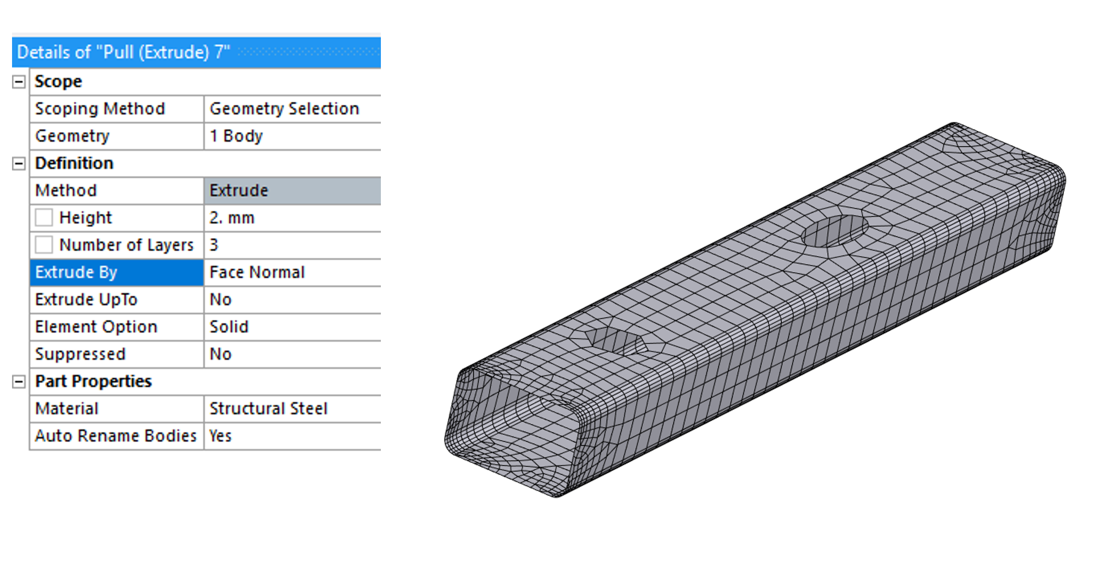
In our hypothetical Ansys Mechanical Pull Tool case, we will mesh a square tube-like geometry with some holes on it. Because this is a shell body, we can easily control the mesh and have a more structured distribution specifically on the corners for example, if desired. All this with less necessary work compared to an equivalent full 3D geometry.
The scope is the full shell body, to include the closed surfaces loop. We defined 2 mm Height which will act as the tube thickness and three elements across the wall. If the base body mesh is quadratic, then the solid elements generated will be quadratic as well.
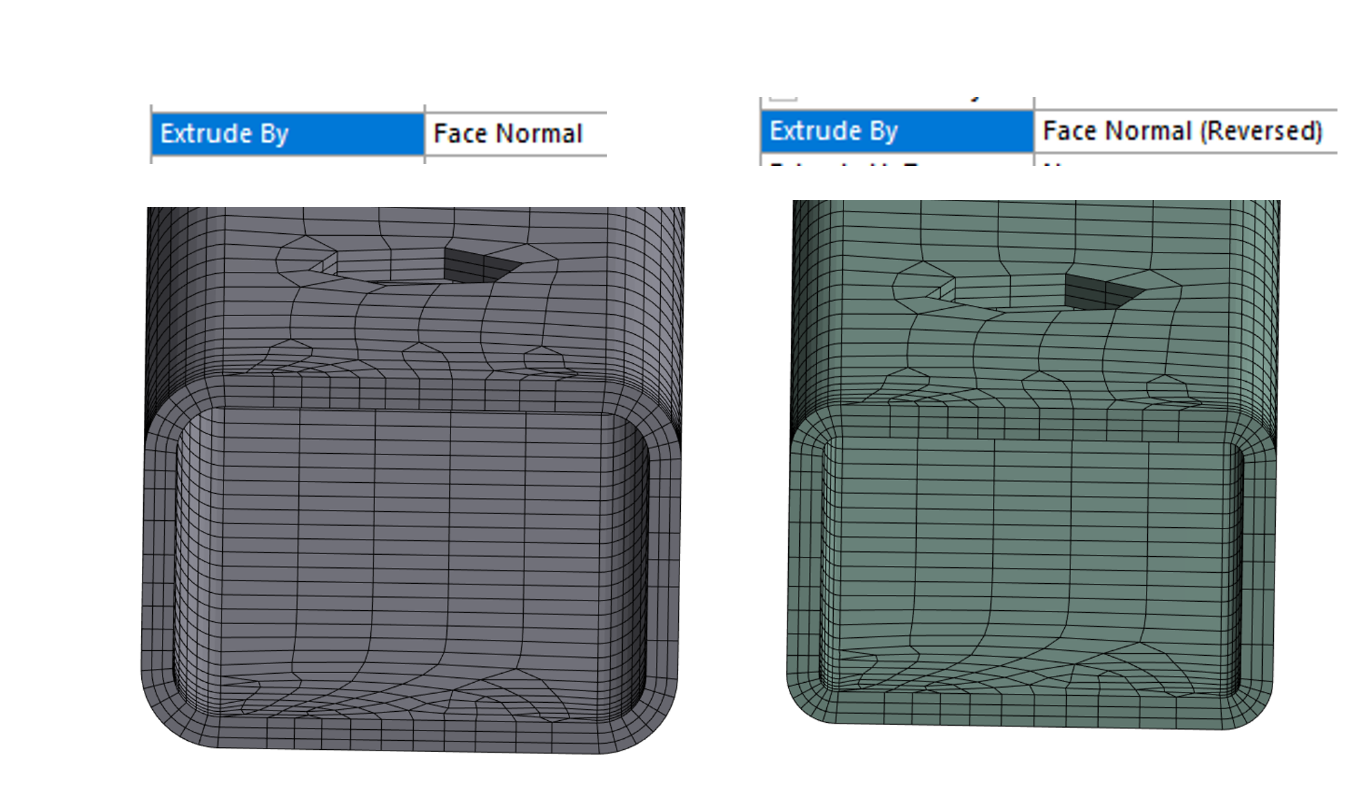
You can use ‘Face Normal (Reversed)’ to extrude in the opposite direction of the surface normal. If the base face belongs to a solid body, the resultant new body will grow inside the initial body.
Extrude Upto: Allows you to generate elements up to the specified target. The target can be faces from solids or sheet bodies and multiple faces with sharing geometric edge.
Extruded By: Allows you to specify the direction of extrusion. The available options are Use Coordinate System, Face Normal and Face Normal (Reversed).
Fourth Example: Custom Direction
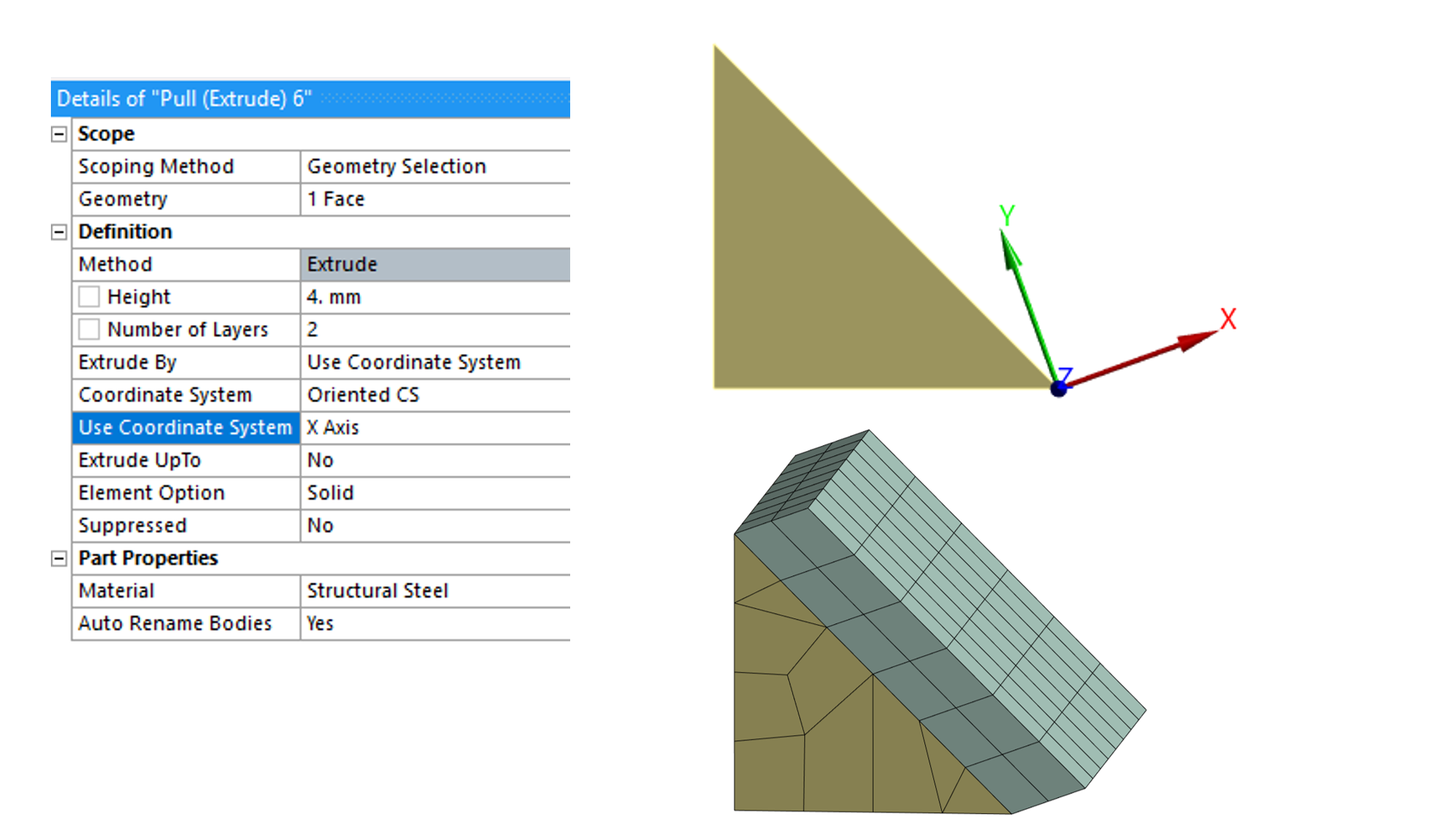
If we want to use a different direction to the surface normal, we can define a coordinate system and reference the extrusion direction to this new orientation. The other options are used as shown in previous examples. Note that is not possible to use UpTo feature, if the ‘No’ value is changed to ‘Yes’ the extrusion will be made in the normal direction.
Fifth Example: No Constant Height
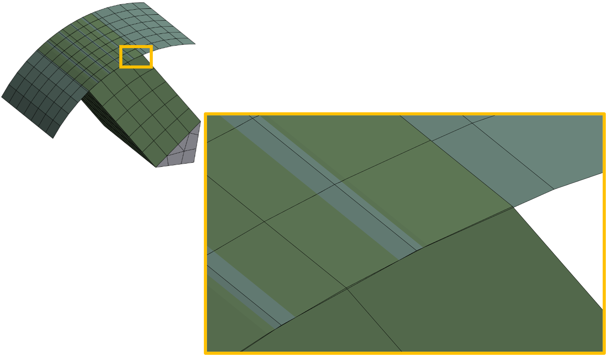
What about no constant height? It is possible to use the ‘UpTo Target’ property again and select a non-planar or tilted surface. Remember the extrusion will be made in the normal direction. The Pull object looks the same as the one shown in the second example.
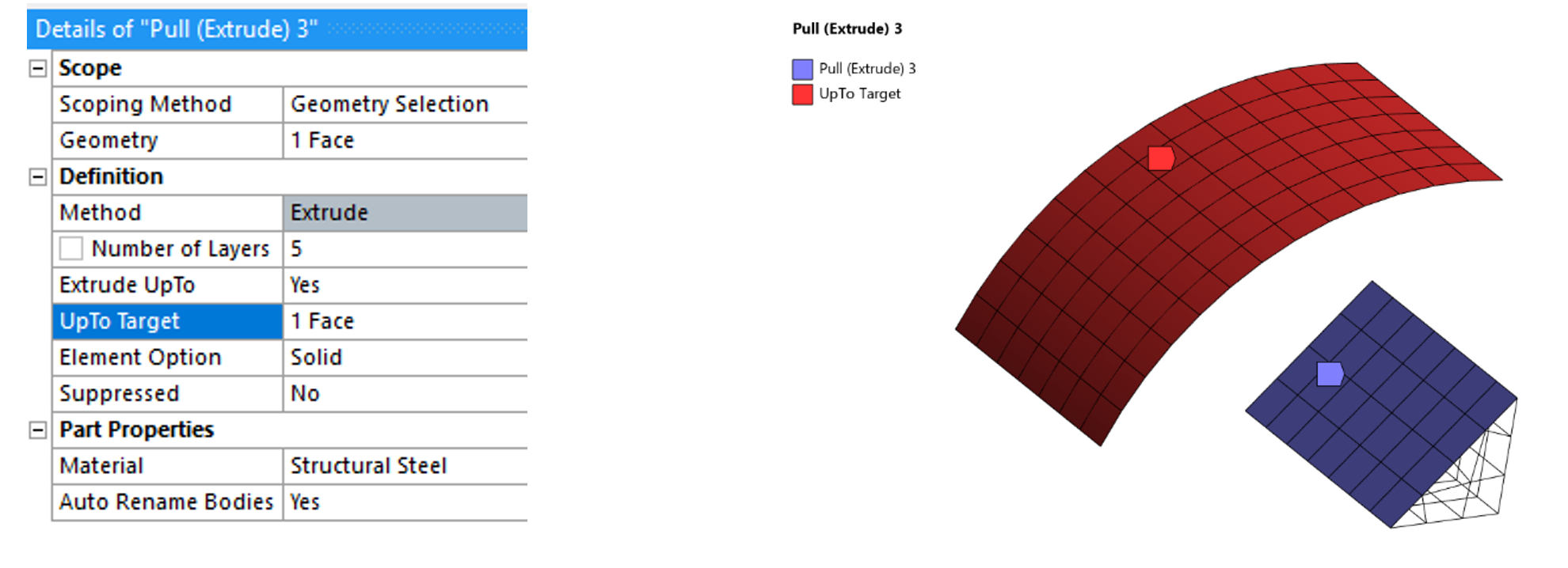
Please note that the mesh density will affect the generated mesh again.
Sixth Example: No Constant Height and Complex Shape
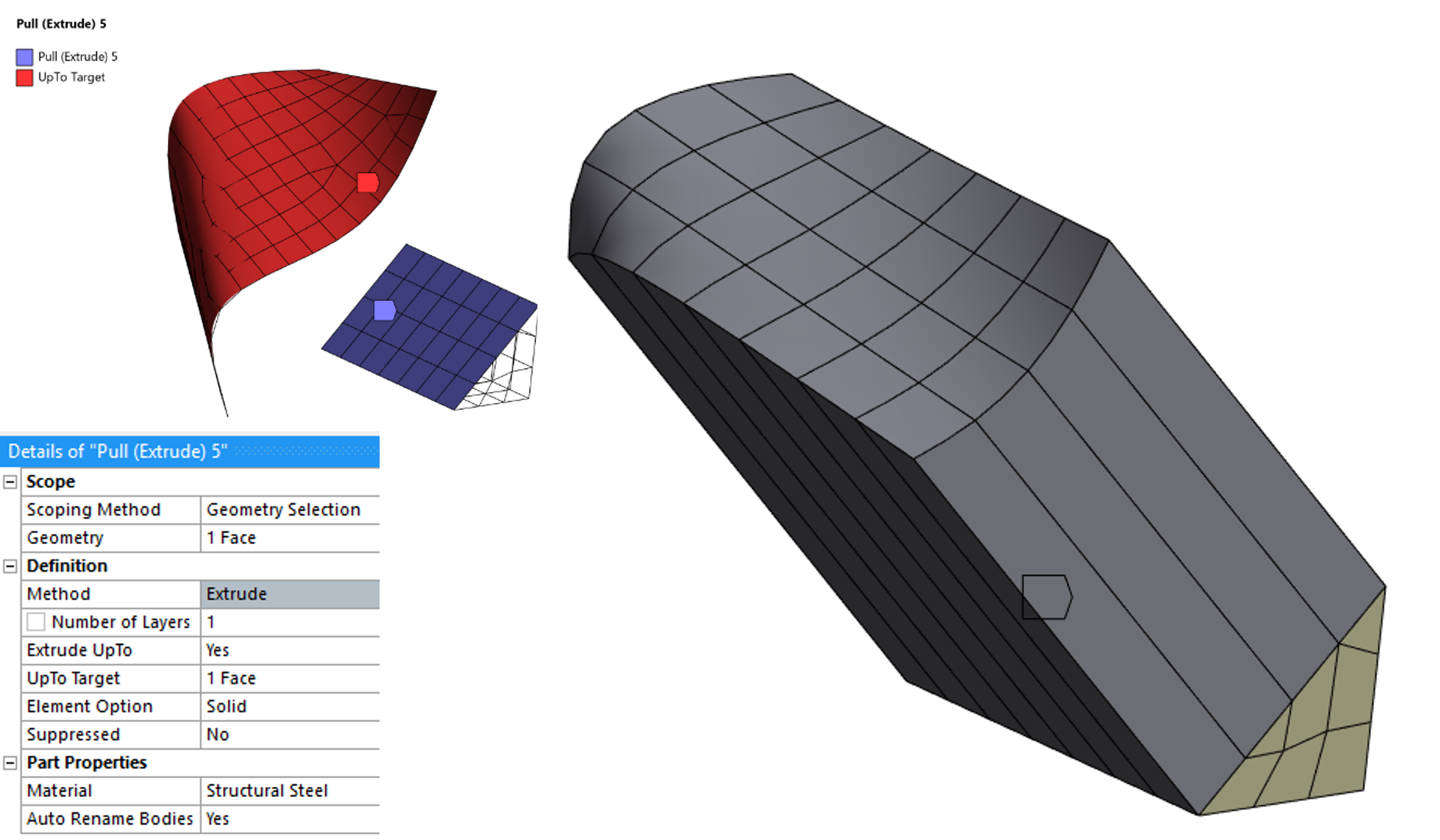
To finish this round of Ansys Mechanical Pull Tool examples, A more complex shape is used as ‘UpTo Target’ with just one layer. Again, the extrusion direction is normal, the final curved shape is mesh size dependent and any projected face out of the ‘UpTo Target’ face will be dropped off.
Revolve
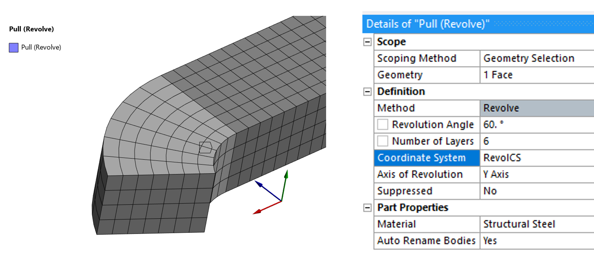
The Revolve option offers fewer settings than the Extrude option and the input data is self explanatory. We need a base surface, a rotation axis from a properly placed coordinate system and the revolution angle accompanied by the number of layers.
Surface Coating
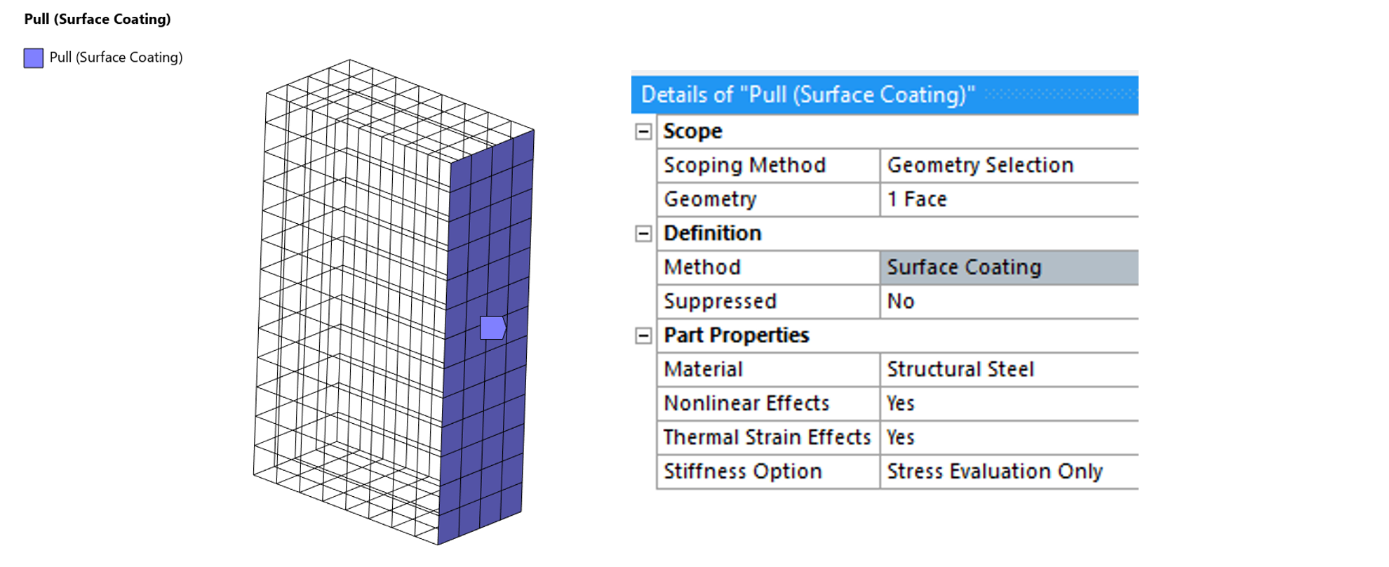
Last option is creating a shell mesh over a solid boundary face. In this case, the nodes are shared between the solid base and the new shell elements. For this shell mesh, it is possible to define Nonlinear effects, Thermal strain effects and Stiffness option.
The Ansys Mechanical Pull Tool: In Conclusion
The Pull tool is much more versatile than its simple interface might suggest. While many users associate it only with basic mesh extrusion, it can be an effective method for generating structured solid meshes, creating thin-walled volumetric models from shell meshes, following complex target geometries, and producing shell coatings directly from existing meshes.
As shown throughout the examples, the final mesh quality depends heavily on the quality and density of the source mesh, especially when using the UpTo Target option with non-planar or irregular surfaces. Understanding these limitations allows the user to take full advantage of the tool and avoid unexpected results.
One particularly useful application is the rapid creation of hexahedral-dominant meshes from well-structured surface meshes, which can significantly reduce modeling effort compared to traditional geometry-based meshing workflows. For thin-walled components, this approach can also provide greater control over mesh topology while maintaining a relatively simple modeling process.
Although the Pull tool may not replace dedicated meshing methods for every application, it is a valuable addition to the analyst’s toolbox and can offer efficient solutions for several challenging meshing scenarios. Taking the time to experiment with its different options can reveal opportunities to simplify model preparation and improve mesh quality in everyday simulation work.
As with many advanced features in Ansys Mechanical, the best way to understand the Pull tool is simply to experiment with it. Small test models can quickly reveal behaviors that are not immediately obvious from the documentation. Hopefully, the examples presented here encourage you to explore this tool further and discover new ways to simplify your meshing workflow.
Want to get more from Ansys Mechanical? SimuTech Group can help with software, training, technical support, and structural simulation consulting.

Edwin Rodriguez Cachaya
Sr Staff Engineer – Structures, SimuTech Group
Edwin is a Sr Staff Engineer – Structures at SimuTech Group specializing in finite element analysis, computational modeling, and structural simulation. His experience includes Ansys Mechanical, APDL, LS-DYNA, nCode, CAD preparation for simulation, virtual prototyping, and technical training. He has also spent more than a decade teaching engineers how to use Ansys simulation tools effectively.