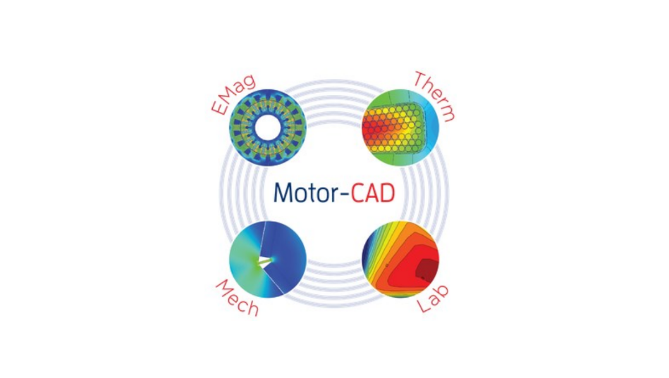
In this blog, I give an overview of how to use Ansys Motor-CAD, simulate, analyze, and post-process results to evaluate motor performance, help you select an optimized motor for your application, and achieve cost-effectiveness and efficiency in your motor design selection. I go over the various motor types available, physics modules to choose from, and multi-physics options to configure. Ansys Motor-CAD is an exclusive motor design tool that can solve analytical motor models and provide 2D FEA results. The models can be solved for single physics (electromagnetic, thermal, and mechanical) or coupled together to solve a unified physics model of the motor. Also, the LAB module can be used to apply complex duty cycles and generate efficiency maps to evaluate the motor’s performance.
TYPICAL USES OF MOTOR-CAD
Motor-CAD is often used for the following tasks:
- Design Optimization — Motor-CAD can be used as an integral part of the design process. By optimizing the electromagnetic model in parallel with the thermal circuit and mechanical design, a true optimum design is achieved. Often, the thermal design aspects are left until the end of the design process, at which point it is too late to alter the design and a sub-standard motor is produced.
- Rapid Response to Customer Inquiries — Often, a customer wishes to use an existing motor for a given application that has a specified load characteristic. Motor-CAD can be used to rapidly model the load specification using its duty-cycle analysis capabilities. The designer then has a clear understanding of whether the motor/drive combination is adequate for the task, and the customer has a sense of security that the designer has fully investigated their inquiry, which helps win orders.
- Rapid Quantification of Design Changes —Occasionally, a change in material or manufacturing process may be proposed. Motor-CAD allows the designer to quickly quantify the effects of such changes on the motor’s performance.
- Program Validation — It is easy to compare the Motor-CAD calculation of the machine performance with tests on existing motors. In carrying out such validation, the user gains a deep understanding of the main parameters that affect the machine’s performance and can use this knowledge to improve the design.
- Parameter Estimation — Often it is very difficult, if not impossible, to directly measure certain key parameters that affect a motor’s performance, e.g., interface gaps, rotor losses. In many cases, these parameters can be estimated by matching Motor-CAD output to readily measurable data, e.g., component temperatures and stator losses. For instance, the interface gap between the stator-lamination and the housing can be varied until it matches the measured values of T[stator] & T[housing].
- Sensitivity Analysis and Robust Design — It is very easy to vary input parameters and examine their effects on machine performance, temperature distributions, etc. Sensitivity analysis can be used on parameters such as dimensional tolerances, material properties, impregnation goodness, interface gaps, etc., and plot a graph of the variation in machine performance. This can be used to gain insight into the critical design variables of the machine. It can also be extended to form part of a system model in Robust Design techniques such as 6-Sigma. The entire calculation process, along with the variation in relevant parameters, can be automated using ActiveX technology or the built-in Sensitivity Analysis tool.
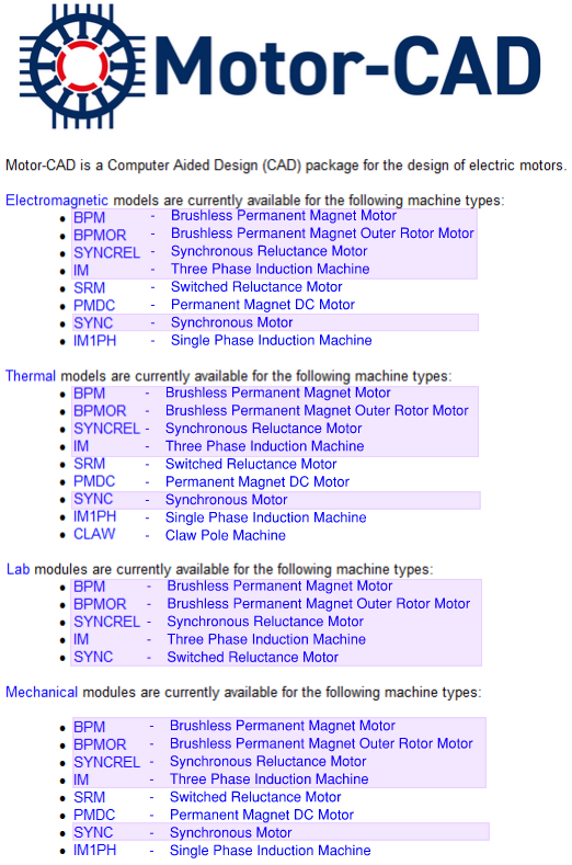
Motor Types Available in Ansys Motor-CAD
Ansys Motor-CAD has nine industry-standard motor types to choose from, and five of these types (highlighted in purple below) are available for design of experiments to develop torque vs. speed curves and produce efficiency maps to evaluate motor performance across various motor drive cycles.
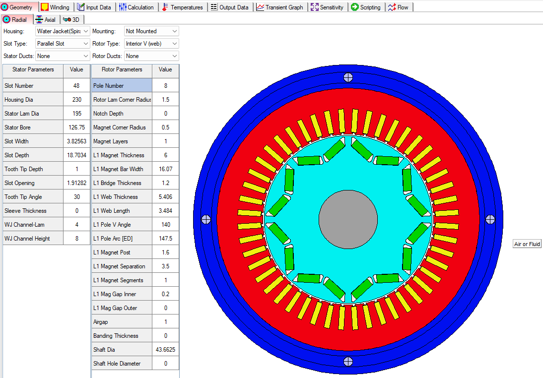
Geometry Template Setup
Ansys Motor-CAD uses templates to create the motor geometry. Below is a template for a Brushless Permanent Magnet motor, for example. Each motor design will have specific geometric parameters for the selected motor type. Also, Motor-CAD has tabs for radial, axial, and 3D views. Each physics module will show relevant geometry for the selected module. For example, the Thermal physics module shows the parameters and geometry for the motor jacket or enclosure if one is selected.
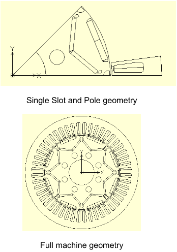
Alternatively, the user may import DXF files for the motor geometry, provided the geometry is close to the standard geometry. It is recommended to use a single-slot/pole DXF geometry, if possible, as this allows Motor-CAD to leverage machine symmetry to reduce computational time. If a full machine custom DXF geometry is used, Motor-CAD will always solve the full machine and will therefore take longer.
In order to use an imported DXF geometry, it must obey the following requirements:
1. The rotation axis must be centered on the origin (0, 0).
2. The imported stator and rotor components must be oriented so that the lower edges of
Each sector is aligned on the x-axis.
3. The airgap boundaries must be formed by concentric circles or arcs forming a smooth,
continuous inner and outer surface. This requires that all slot openings be closed and
any eccentricity on either surface is buffered from the airgap mesh region by arcs
centered on the origin.
4. Each slot region needs to be divided into two regions so that the current density
can be assigned correctly.
5. The positions and alignment of the DXF geometry must match those of the single slot
and pole or full machine geometries below.
6. The DXF file must be saved in R12 ASCII drawing format.
Electromagnetics (EMag) Module
The E-Mag physics module has many tabs covering all the settings for geometry creation, material selection, electromagnetics settings, conditions, solver types, solution models, coupling settings, etc.
Electromagnetic Model
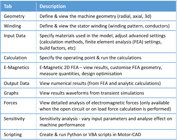
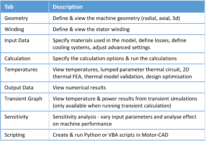
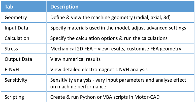
The following main tabs are available in the E-Magnetic context for sine-wave driven BPM
machines. Generally, in Motor-CAD, we work through the tabs from left to right in order to set
up the model, run the calculations, and analyze the results.
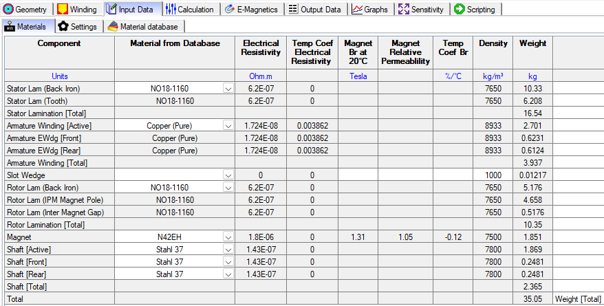
Electromagnetic Model – Material
The materials tab has relevant physics parameters for the Electromagnetics module.
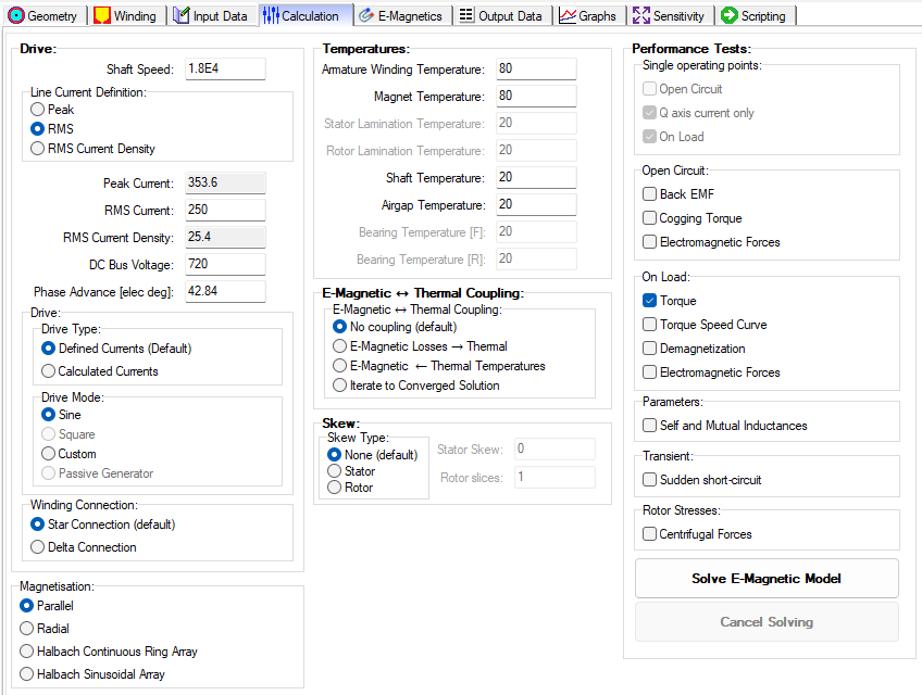
Electromagnetic Model – Calculation
The Calculation tab has relevant settings and options for the Electromagnetics module.
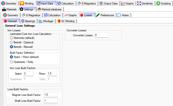
Electromagnetic Model – General Loss Settings
Apply the Steinmetz model to ferrite material and the Bertotti model to electrical steel material. Also, there are various models for bearing losses, windage, and AC winding losses.
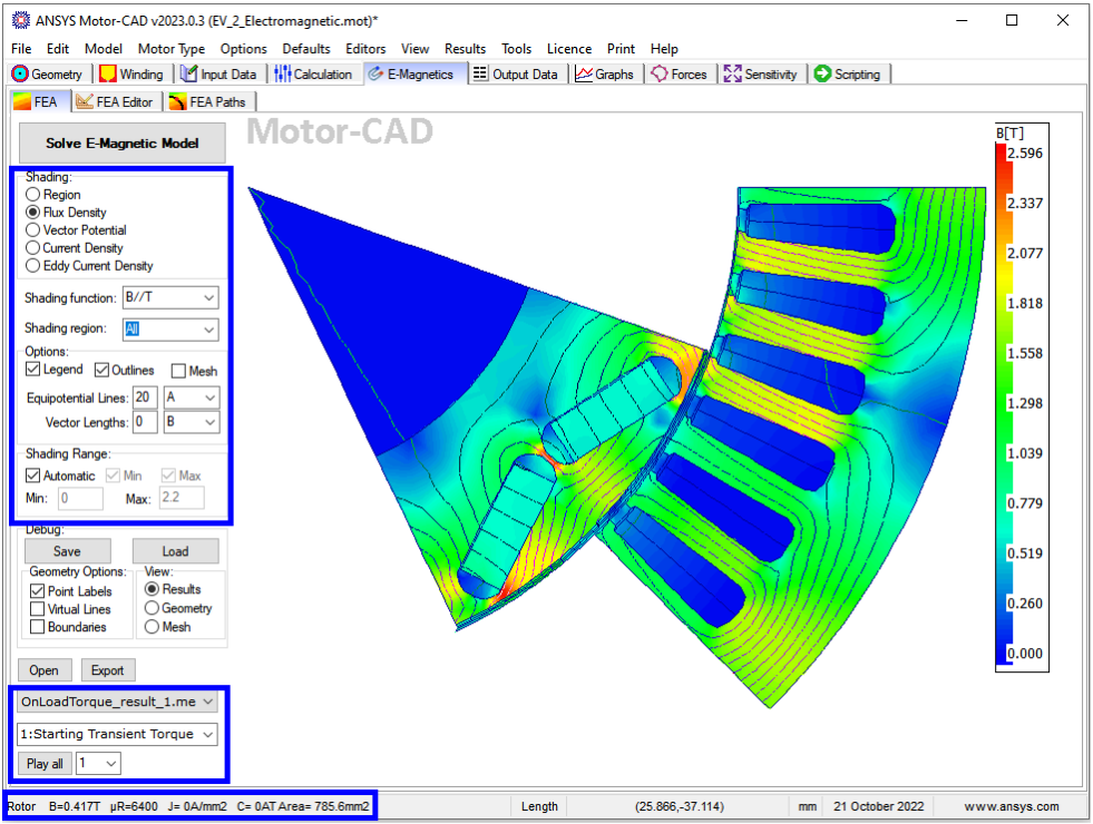
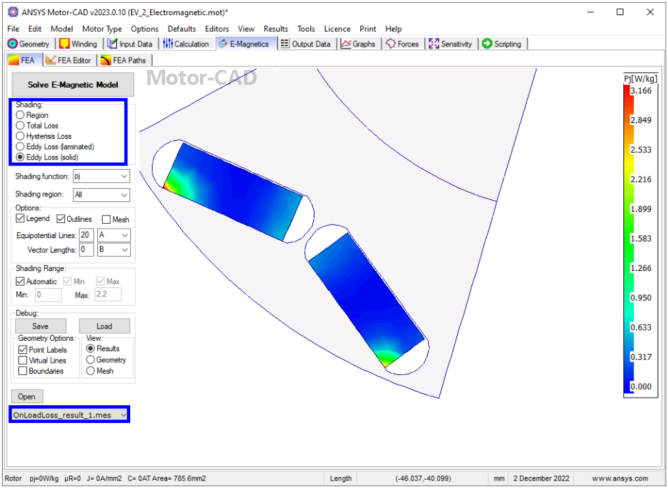
Electromagnetic Model – Analysis
The E-Magnetic module in Motor-CAD allows 2D FEA electromagnetic analysis and loss
calculation to obtain the working conditions and performance of the machine. It also has an
automatic link to the thermal model in Motor-CAD for subsequent thermal analysis.
Heat Transfer (Thermal) Module
The Thermal physics module has many tabs to cover all of the settings for the geometry creation, material selection, thermal settings, conditions, solver types, solution models, coupling settings, etc.
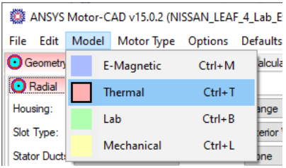
Thermal Model
The thermal model in Motor-CAD solves lumped parameter thermal networks in order to obtain
the working temperatures of the machine. FEA thermal simulations can also be used in order
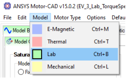
to validate the lumped parameter model. Switch to the thermal context with Model -> Thermal or Ctrl+T (tip: a red background on the active tab indicates thermal context). Save the file as EV_5_Thermal.mot.
The following main tabs are available in the thermal context:
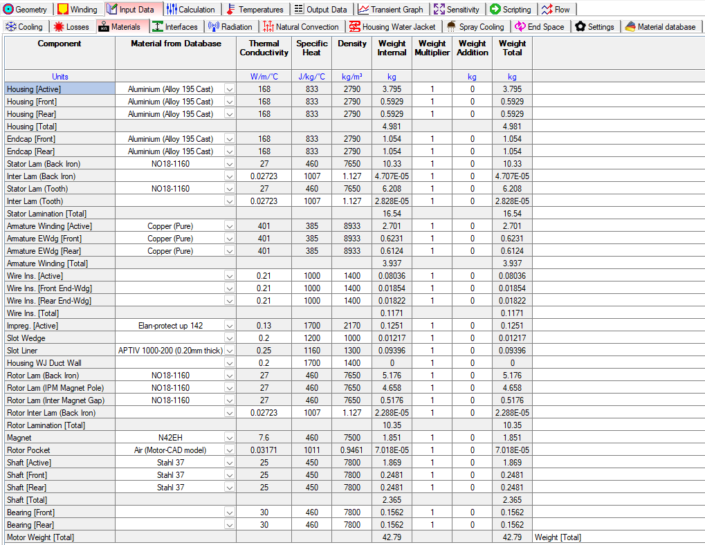
Material Settings
The materials tab has relevant physics parameters for the Thermal module.
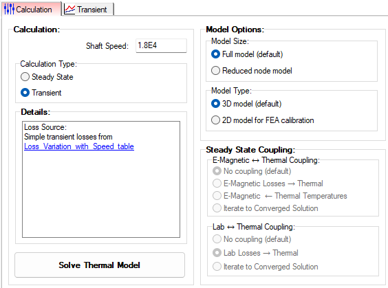
Calculation Settings
The Calculation tab has relevant settings and options for the Thermal module.
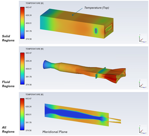
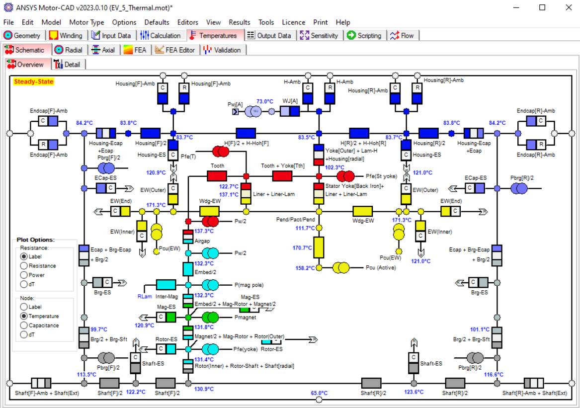
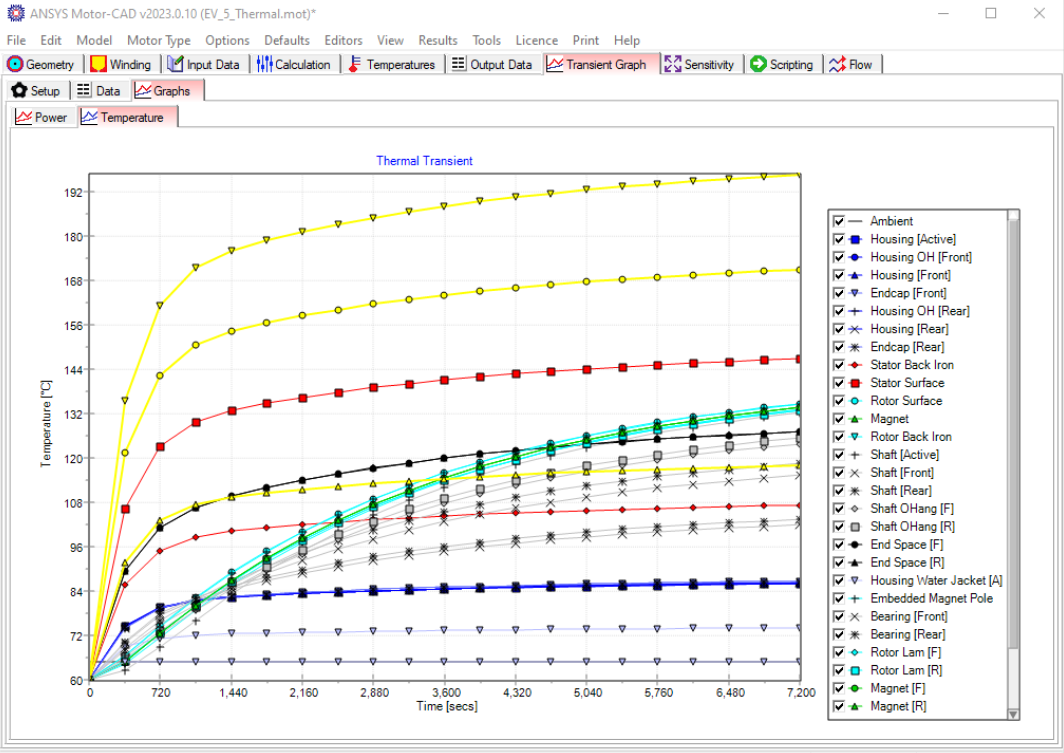
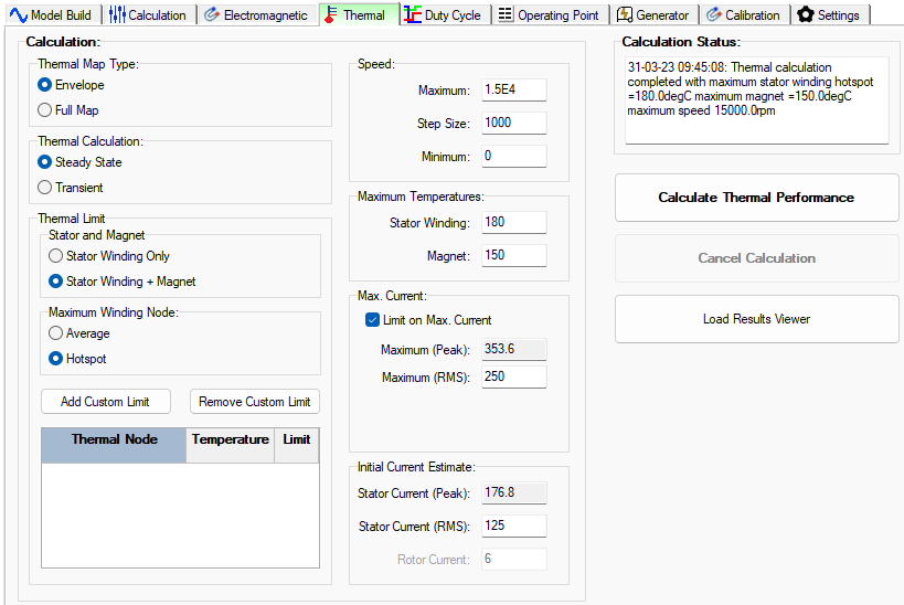
Thermal Analysis
Based on the input geometry, losses, and model settings, Motor-CAD creates a 3D lumped
parameter circuit model to
- Characterize the thermal behavior of the machine for steady-state or transient calculations
- Handle simple or complex duty cycles
- Evaluate continuous thermal performance with Lab coupled with Thermal
Each component is represented with a thermal resistance and capacitance. Losses are represented as power sources, and power is dissipated to the ambient node by the cooling systems. By solving this equivalent thermal circuit, Motor-CAD can accurately estimate the temperatures in each part of the machine.
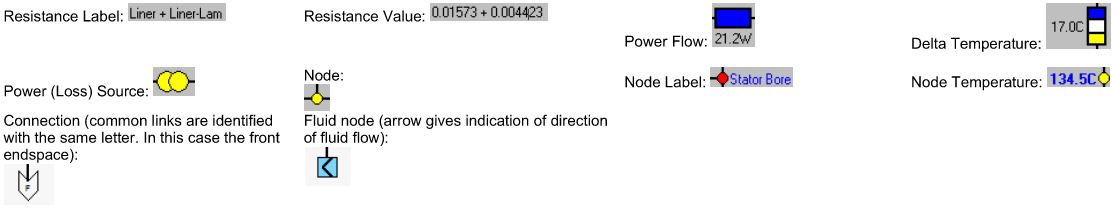
Legend:

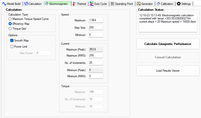
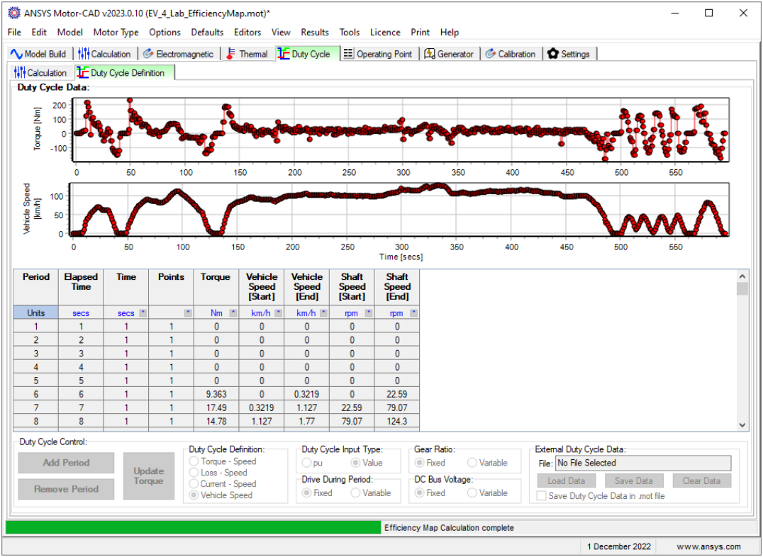
Lab Module: Motor Performance Evaluation
The Lab design of experiments has many tabs to cover all of the settings for the geometry creation, material selection, thermal settings, conditions, solver types, solution models, coupling settings, etc.
Lab Model
Motor-CAD’s Lab module allows us to quickly and accurately calculate the machine
performance over the full operational envelope, and can be used to
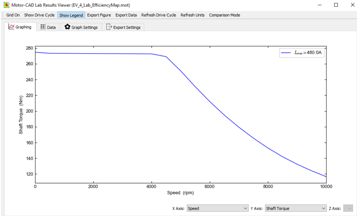
- Estimate peak torque/speed
- Develop a family of torque vs. speed curves
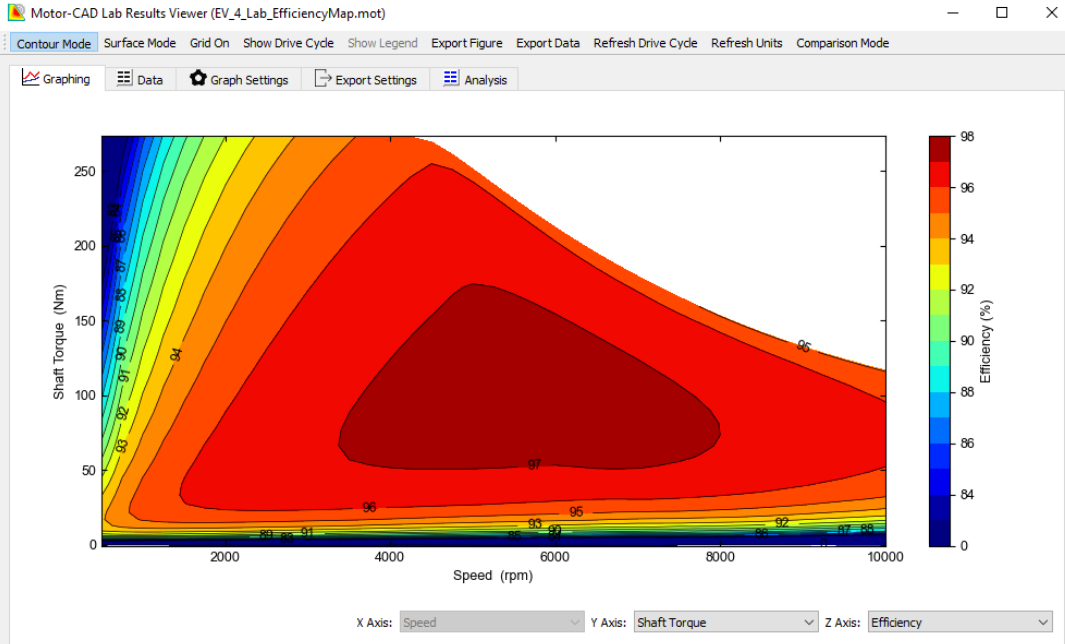
- Create efficiency maps
- Study the thermally constrained operational envelope
- Analyze performance over complex driving cycles
The following tabs are available in the Lab context:
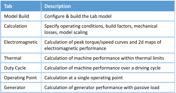
Lab Analysis
The Lab module uses a hybrid model that combines the accuracy of FEA calculations with the
speed of analytic results. We first built the Lab model, performing a series of FEA simulations
to fully characterize the saturation and loss behavior of the machine. Once this model
is complete, we use it to accurately calculate the machine performance with analytic methods.
Mechanical Module
The Mechanical physics module has many tabs to cover all of the settings for the geometry creation, material selection, mechanical settings, conditions, solver types, solution models, coupling settings, etc.
Mechanical Model
The Mechanical module in Motor-CAD uses 2D finite element simulations links to the
electromagnetic model in Motor-CAD, for detailed analysis of
- Stress and displacement in rotors during operation
- NVH performance under different operating conditions
The following main tabs are available in the mechanical context:
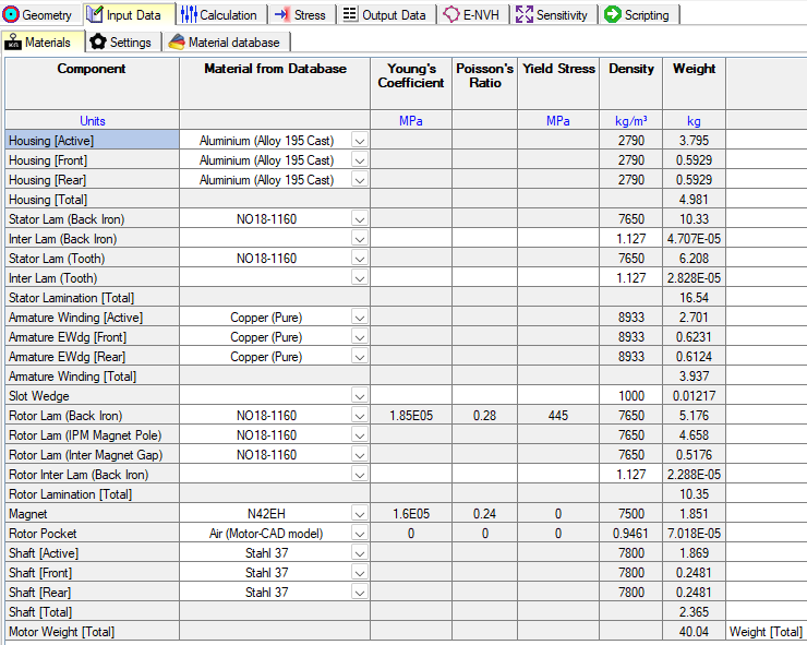
Material Settings
The materials tab has relevant physics parameters for the Mechanical module.
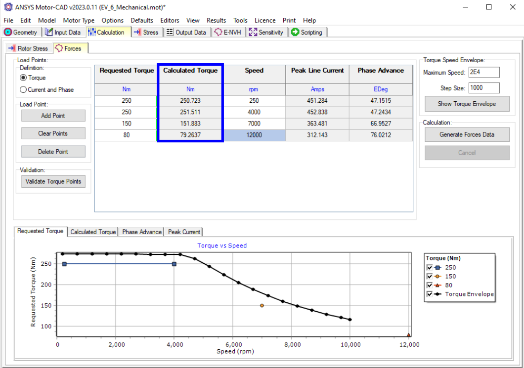
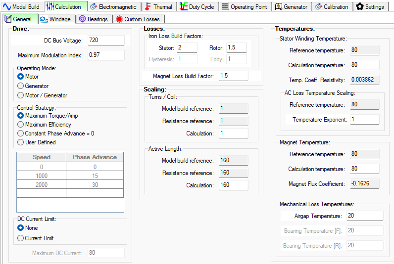
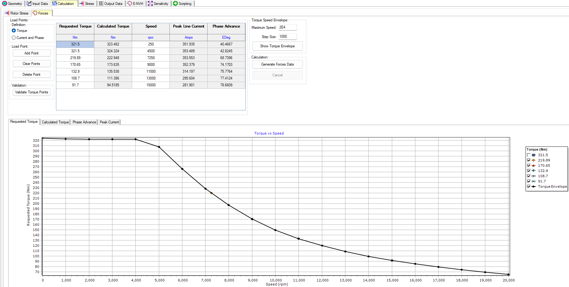
Calculation Settings
The Calculation tab has relevant settings and options for the Mechanical module. The requested torque and speed are input by the user, and Motor-CAD calculates the required torque. Corresponding Peak Line Current and Phase Advance calculations for the operating points are obtained as close as possible to the requested inputs.
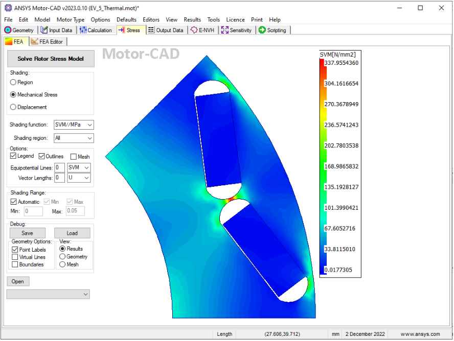
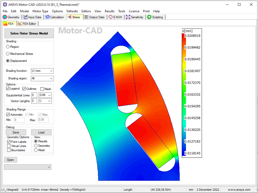
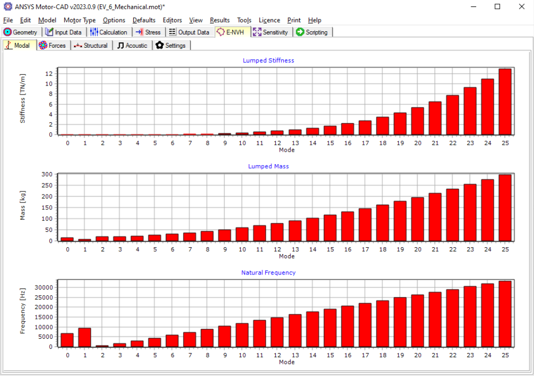
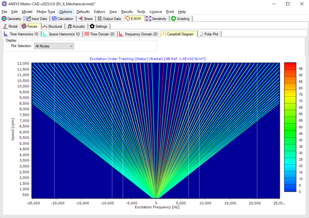
Mechanical Analysis
Motor-CAD allows engineers to consider mechanical and electromagnetic performance trade-offs during design optimization. Some of the mechanical results you can obtain in Motor-CAD are:
- Rotor stresses
- Displacements
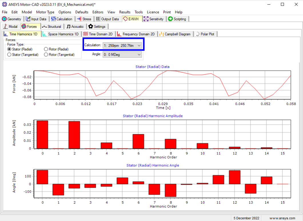
- Stator forces from torque speed curves
- Time and space force harmonics
- Modal analysis
- Excitation tracking