Contact Us
Introduction to Multilayer Coextrusion Simulation
Extrusion is a widely used manufacturing process for producing continuous profiles with constant cross-sections. In its simplest form, a polymer is melted and forced through a die to produce products such as films, sheets, pipes, and technical profiles. The process is valued for its high productivity, scalability, and ability to manufacture complex geometries at relatively low cost, which explains its extensive use across packaging, construction, automotive, and medical industries.
However, many modern applications require a combination of properties that cannot be achieved with a single material. For instance, food packaging films often need mechanical strength on the outside, barrier protection against oxygen or moisture in the middle, and sealing capability on the inner layer. Similarly, industrial pipes may require different functional layers to provide structural integrity, chemical resistance, and long-term durability. These needs have led to the development of multilayer or coextrusion technologies.
Multilayer extrusion enables the combination of different polymers into a single structured product, where each layer performs a specific function. Common materials include commodity polymers such as polyethylene (PE) and polypropylene (PP), engineering polymers like polyamide (PA) and ethylene-vinyl alcohol (EVOH), and tie layers that ensure adhesion between otherwise incompatible materials. By adjusting layer configuration and material selection, manufacturers can tailor product performance to highly specific requirements.
From a process standpoint, multilayer systems require coordinated feeding of multiple polymer streams into a die or feedblock system. The final product quality depends on the ability to maintain stable flow distribution and consistent layer architecture throughout the process.

Challenges Multilayer Coextrusion Simulation Helps With
Although multilayer extrusion is a mature industrial technology, its operation and design still present significant challenges for engineers and manufacturers. Modern production lines are capable of handling multiple polymer streams simultaneously and producing complex layered structures at high throughput. However, achieving consistent product quality across long production runs remains a critical issue.
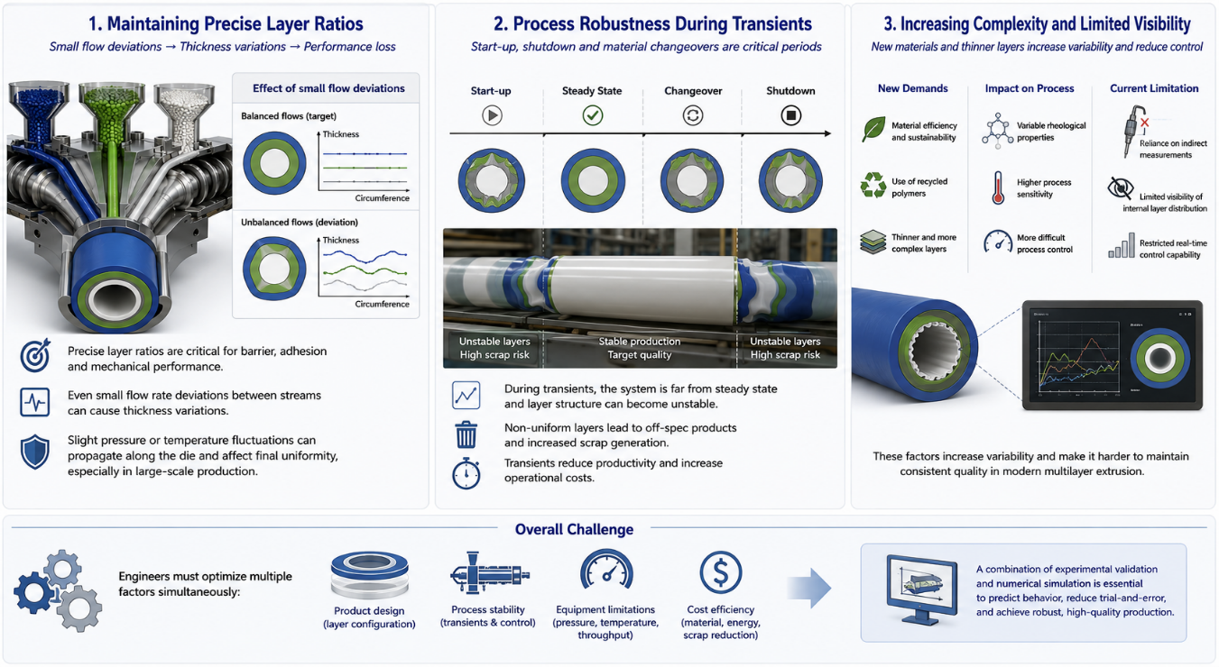
One of the main industrial challenges is maintaining precise layer ratios under real operating conditions. Even small deviations in flow rate between polymer streams can lead to thickness variations that compromise functional performance, particularly in thin barrier or adhesive layers. This sensitivity becomes more pronounced in large-scale production, where slight fluctuations in pressure or temperature can propagate along the die and affect final product uniformity.
Another key difficulty lies in process robustness during transients such as start-up, shutdown, or material changeovers. During these periods, the system is far from steady state, and layer structure can become unstable, leading to significant scrap generation. This represents an important economic and operational concern in continuous manufacturing environments.
In addition, increasing demands for material efficiency and sustainability are pushing the use of thinner layers, recycled polymers, and more complex material combinations. These trends increase variability in rheological properties and make process control more difficult. At the same time, industrial systems still rely heavily on indirect measurements, limiting real-time control of internal layer distribution.
As a result, engineers must optimize not only product design, but also process stability, equipment limitations, and cost efficiency simultaneously, often relying on a combination of experimental validation and numerical simulation tools.
Engineering Methods
Methods
In industrial multilayer extrusion, process design is based on a combination of engineering calculations, experimental validation, and practical experience. The process begins by defining the required layer architecture according to product functionality, including material selection and target layer thicknesses. Engineers then perform simplified calculations to estimate key variables such as pressure drop, flow distribution, and throughput balance between multiple extruders. The main objective with is to ensure that each polymer stream delivers the correct flow rate to achieve the desired layer ratios at the die exit while maintaining overall process stability.
Once the initial design is defined, pilot-scale or industrial trials are used to validate performance. These experiments allow evaluation of layer uniformity, interfacial quality, and sensitivity to operating conditions such as temperature, screw speed, and viscosity differences. This step is essential to identify practical limitations that are not fully captured in simplified analytical models. It also helps to address known challenges such as flow imbalance and instability under transient conditions.
However, experimental development alone is often costly and limited in its ability to provide detailed insight into internal flow behavior. For this reason, numerical simulation is increasingly used as a complementary tool. It helps predict flow distribution and layer formation inside dies and feedblocks, supporting design decisions before physical testing. Overall, modern practice relies on a hybrid workflow combining calculations, experiments, and simulation to improve robustness and reduce development time.
Solutions
In modern multilayer extrusion, multilayer coextrusion simulation using computational fluid dynamics (CFD) has evolved from a supportive engineering tool into an essential component of process design and optimization. While experimental trials and analytical calculations remain important, they are no longer sufficient on their own to address the increasing complexity of multilayer systems. The demand for tighter tolerances, thinner functional layers, and more diverse material combinations has made process understanding at the internal flow level a critical requirement rather than an optional advantage.
CFD enables engineers to analyze the detailed behavior of polymer melts inside feedblocks and dies, where direct experimental measurements are often limited or impossible. Key aspects such as velocity distribution, pressure gradients, interfacial deformation, and layer stability can be predicted before manufacturing equipment is built or modified. This significantly reduces development time, minimizes costly trial-and-error iterations, and improves confidence in design decisions.
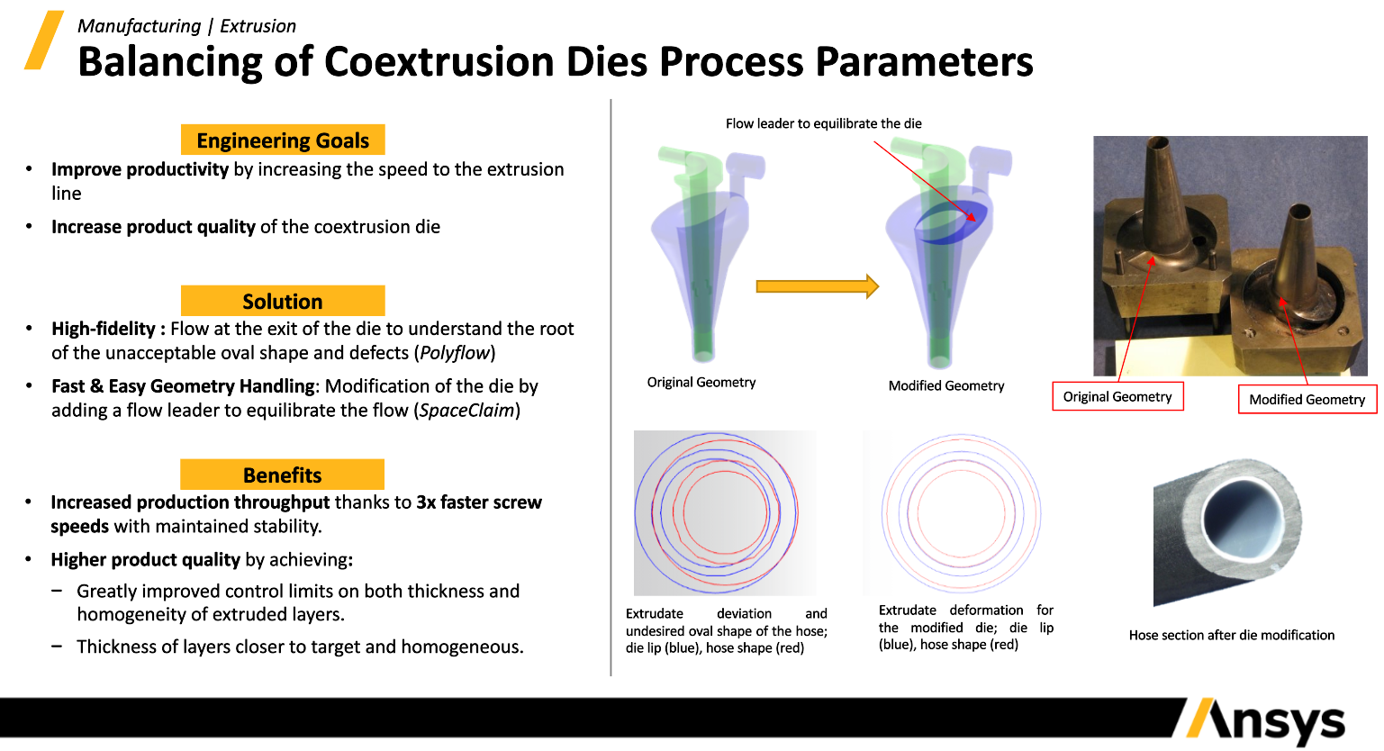
Within the industry, specialized tools such as Ansys Fluent and its Polyflow capabilities are widely used for polymer processing applications. These platforms are particularly suited for non-Newtonian fluid behavior, free-surface tracking, and multilayer flow analysis, making them highly relevant for coextrusion systems. They allow engineers to replicate realistic processing conditions and evaluate how design choices affect final layer structure and stability.
In this context, CFD is not only a simulation tool but a decision-making framework that supports design, troubleshooting, and process optimization. The following section presents a numerical demonstration of a multilayer extrusion system, illustrating how geometry, meshing strategy, setup, and results analysis can be used to gain deeper insight into process behavior.
Multilayer Coextrusion Simulation Workflow for Polymer Processing
Geometry/Mesh
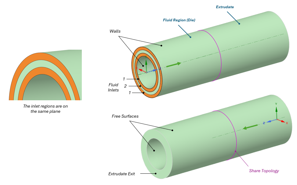
For this demonstration, a simplified coextrusion geometry was selected to illustrate the simulation workflow while maintaining the key characteristics of a multilayer extrusion process. The fluid domain consists of two connected regions: the flow channel inside the die and the downstream extrudate region. These domains were merged using a Share Topology approach to ensure solution continuity across the interface.
The die geometry is based on an axisymmetric cylindrical configuration with three inlets. Two of the inlets are assigned to Fluid 1 (HDPE), while the remaining inlet is assigned to Fluid 2 (LDPE), allowing the formation of a three-layer structure in the final extrudate. To create the multilayer configuration, the inlet surface is partitioned into three independent regions that define the individual polymer streams entering the die.
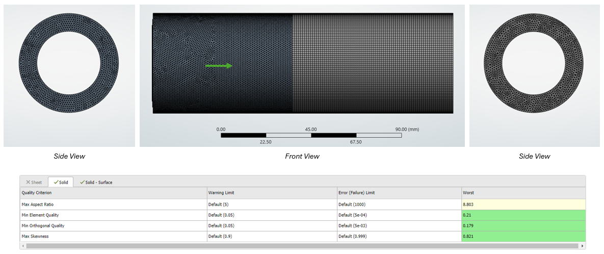
The three-dimensional mesh was generated in Ansys Meshing using tetrahedral elements, resulting in a total of 589,761 elements. It is important that the extrudate region is meshed using a Sweep method and that at least 3–4 elements are used across the thickness to properly resolve the flow. It is also recommended to verify the mesh quality using the Polyflow mesh quality criteria and ensure that all parameters fall within the recommended ranges. In this case, elements with an aspect ratio above 5 are located in the extrudate region, although this can be further improved if necessary.
Multilayer Coextrusion Simulation Model Setup
The model setup is based on the definition of appropriate boundary conditions for each region of the domain.
Inlets. Two fluids were considered in this example, one of which consists of two layers; however, it is also possible to include three or more fluids by modifying the geometry accordingly and adding additional Named Selections to fully define all inlet boundaries. The inlet condition is specified as a volume flow rate, although other options are also available, such as mass flow rate, uniform velocity, or velocity profiles depending on the level of detail required.
Outlet. It corresponds to the extrudate exit, where a take-up velocity is prescribed in the flow direction to control the drawing of the material.
Free Surfaces. These boundaries represent the extrudate region interfaces in contact with the surrounding environment, and a zero gauge pressure condition is applied.
Walls. All are defined as no-slip and stationary; however, alternative formulations such as partial slip or free slip are also available.
Extrudate Region. It is defined by selecting the corresponding cell zone along with the two surfaces that bound this region.
Results
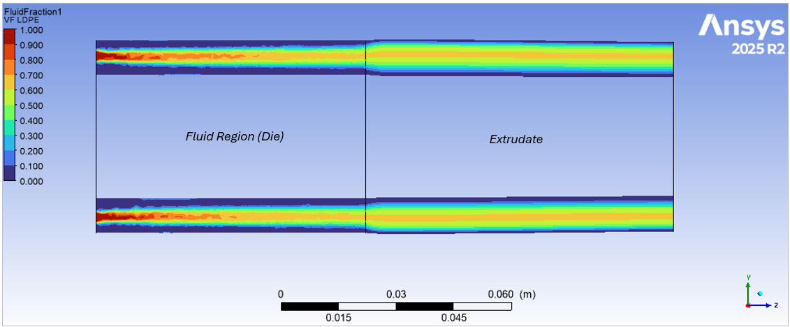
The multilayer coextrusion simulation was executed using 12 CPU cores, requiring approximately 19 GB of RAM and a total solution time of 3.7 hours. The selected operating conditions produced a stable multilayer structure as described as follows.
Volume Fraction Distribution
The volume fraction contours show that the LDPE stream successfully forms the intermediate layer of the multilayer structure, while the inner and outer layers remain occupied by HDPE. The interfaces between materials are smooth and continuous throughout both the die and extrudate regions, indicating that the selected flow rate distribution is capable of maintaining the desired three-layer architecture. Only a slight redistribution of the LDPE layer is observed after the die exit, suggesting that the chosen flow rates and take-up velocity provide a stable extrusion process.
Monitoring Line Analysis
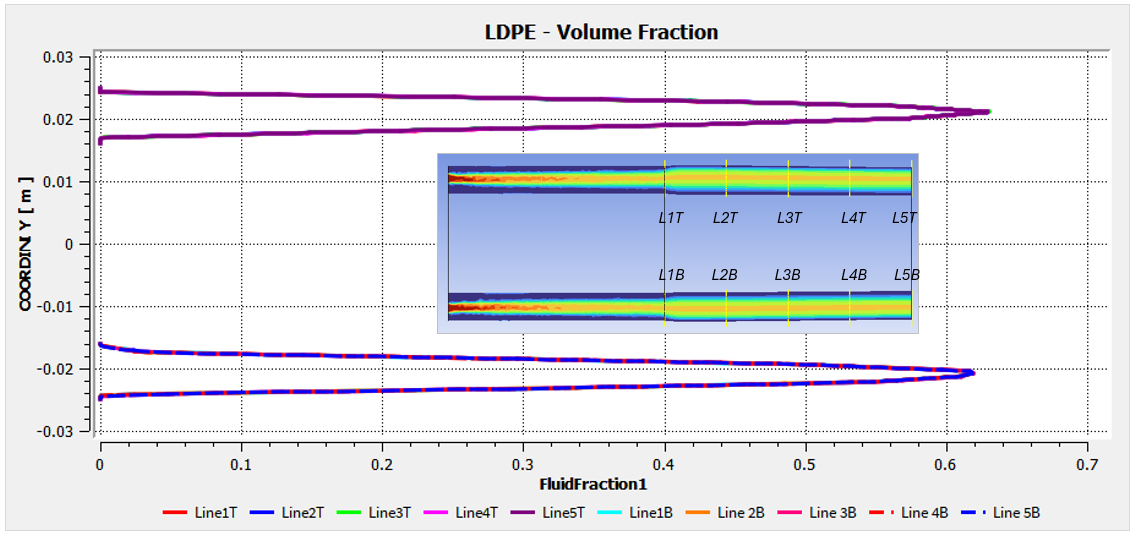
The monitoring lines along the extrudate reveal a nearly symmetric volume fraction distribution with respect to the centerline, confirming the axisymmetric nature of the flow. While small variations are observed near the interfaces, the volume fraction remains largely unchanged within the core of the LDPE layer. This behavior indicates that the interfaces remain stable throughout the extrudate and that the multilayer structure is preserved downstream of the die.
Layer Stability Assessment
An important observation is that the spacing between the monitoring curves remains relatively uniform throughout the entire extrudate region. This indicates that the thickness of the LDPE layer is largely preserved after exiting the die. From an industrial perspective, maintaining a consistent layer thickness is essential because the functional properties associated with the LDPE layer, such as flexibility and sealing performance, depend directly on the uniform distribution of material within the final product.
Need help with a multilayer coextrusion simulation project?
Whether you’re evaluating die designs, balancing polymer flow, or improving layer stability and thickness uniformity, SimuTech Group’s Ansys Polyflow experts can help your team use simulation to better understand internal flow behavior, reduce trial-and-error, and improve coextrusion process performance.

Germán Ibarra, MSc Energy Engineering
Senior Staff Engineer – Fluids, SimuTech Group
Germán Ibarra is a mechanical engineer with a master’s degree in Energy Engineering and more than 14 years of experience in research, development, and engineering analysis. At SimuTech Group, he supports simulation-driven workflows for complex engineering applications, including polymer processing, thermal-fluid behavior, and manufacturing process optimization. His background spans R&D, project development, and technical education, helping engineering teams apply numerical simulation to better understand product performance, reduce physical testing, and improve design decisions.