
 Contact Us
Introduction to Rare-Earth-Free Electric Motors
Rare-earth-free electric motors are gaining attention as manufacturers seek alternatives to conventional permanent magnet designs amid supply chain uncertainty, material costs, and sustainability concerns. Developing these alternatives presents an engineering challenge: maintaining torque, efficiency, and power density without relying on high-performance rare-earth magnets.
Through electromagnetic simulation and design optimization, engineers can evaluate alternative motor configurations, including ferrite-assisted synchronous reluctance motors and electrically excited synchronous motors. This article explores these approaches and demonstrates how Ansys Maxwell, Motor-CAD, and optiSLang support the development and optimization of rare-earth-free electric motor designs.
Understanding Rare-Earth Materials
Rare earths come from the periodic table. They are a group of 17 metallic elements, including the 15 lanthanides along with scandium and yttrium. Despite their name, these elements are not truly rare in abundance, but they are rarely found in concentrated and economically viable deposits.
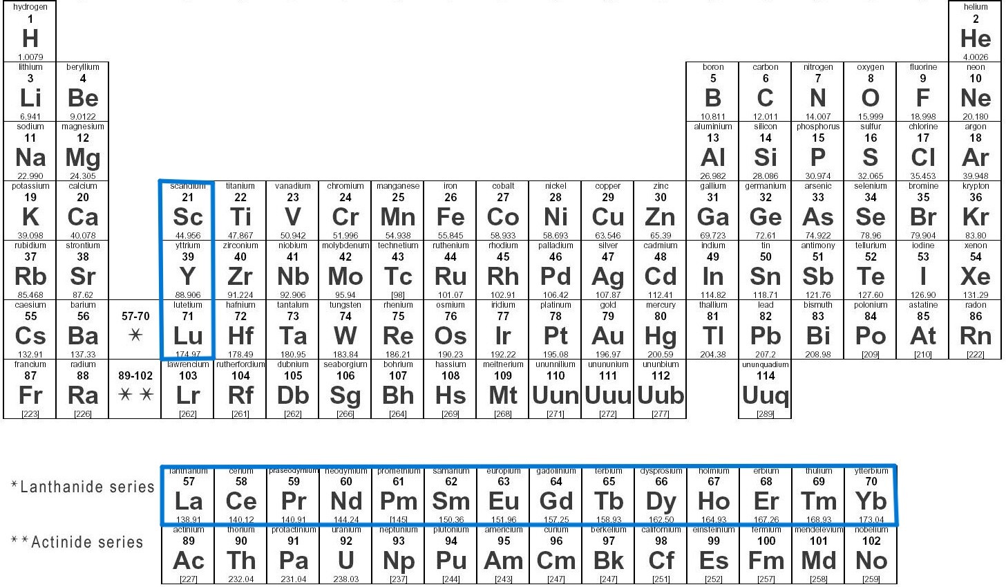
Although they’re called rare-earth elements, these materials are not actually rare in the Earth’s crust. What makes them “rare” is the difficulty of mining, separating, and refining them into usable forms. The extraction process is complex, energy-intensive, and environmentally demanding. Over the past few decades, China has mastered and scaled this refining capability, allowing it to dominate more than 70% of the global rare-earth production and nearly all processing capacity. This dominance has given China significant influence over pricing and supply stability, effectively creating a strategic monopoly that impacts industries from electric vehicles to wind turbines and consumer electronics worldwide.
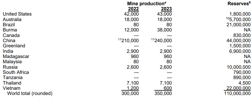
source: U.S. Geological Survey, Mineral Commodity Summaries, January 2024
Why Rare-Earth Magnets Matter in Electric Motors
Most modern electric motors that aim for high efficiency and power density rely on rare-earth magnets because of their exceptional magnetic strength. However, recent geopolitical tensions and policy shifts among nations have revealed a critical vulnerability: high performance means little if the supply chain collapses. The dependence on rare-earth materials not only risks production delays but can also drive up costs as manufacturers scramble to redesign supply chains or source alternative magnets capable of delivering comparable performance.
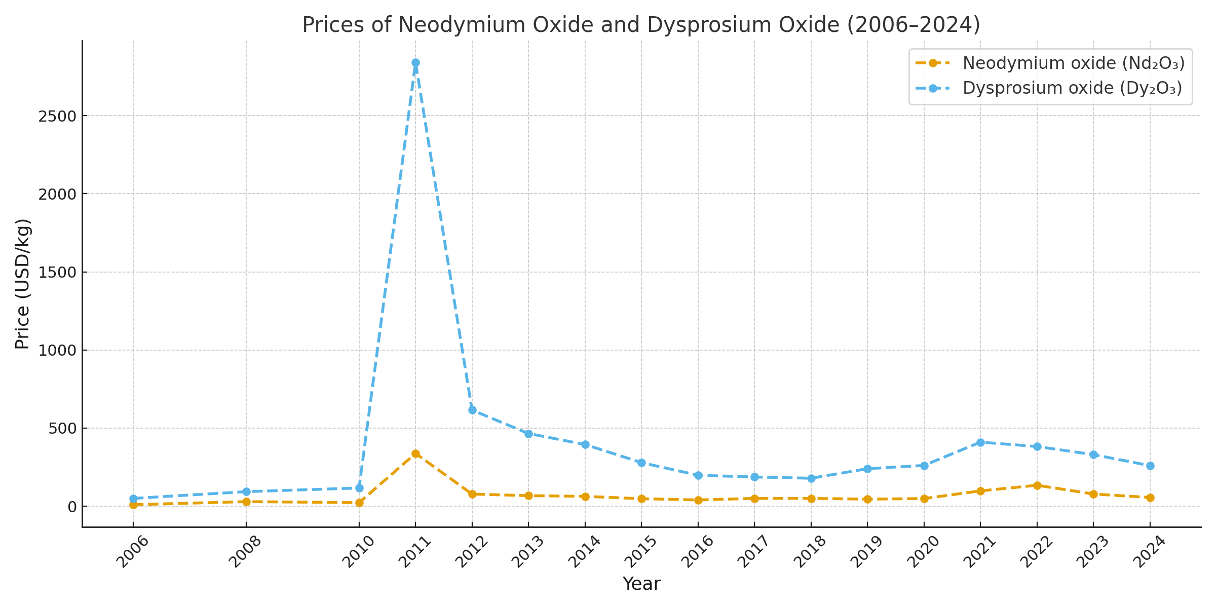
source: U.S. Geological Survey, Mineral Commodity Summaries, January 2024 / Eggert, R., Wadia, C., Anderson, C., Bauer, D., Fields, F., Meinert, L., & Taylor, P. (2016). Rare earths: market disruption, innovation, and global supply chains. Annual Review of Environment and Resources, 41(1), 199-222.
The prices of two critical rare-earth materials — Neodymium and Dysprosium — have become increasingly volatile due to the heavily monopolized supply chain. Following recent developments, it’s clear that this instability makes it difficult for manufacturers to predict the profit margin of each electric motor produced. Such uncertainty can have serious financial consequences, especially for companies that produce motors in large volumes every month.
Exploring Rare-Earth-Free Electric Motor Designs
It is clear that we must either use rare earth free magnets or remove magnets entirely from our motor designs. In this section, we will explore how to design alternative electric motors that do not depend on rare earth materials.
Before exploring these designs, it is important to understand the fundamental principles of electric motors, because solving this challenge begins with understanding where torque actually comes from. In a synchronous electric motor, there are two main sources of torque: mutual (magnet) torque and reluctance torque.
1. Mutual Torque in Electric Motors
At the heart of every electric motor lies the rotating electromagnetic field generated in the stator. The stator’s laminated steel core and organized copper windings are energized by a voltage or current source, producing this field.
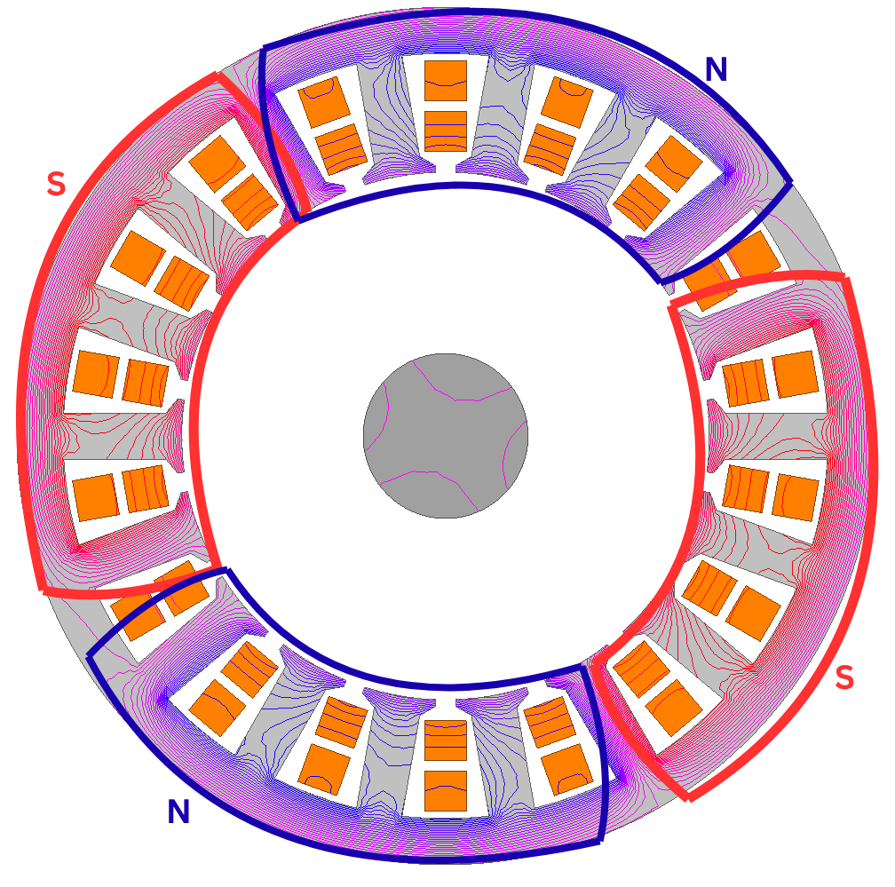
If the supply is DC, as shown in the left image, a 4-pole stationary electromagnetic field is created with this setup. Through magnetic dipole interaction, permanent magnets on the rotor can align or “lock” with this field — but no continuous rotation occurs, since both the field and magnets remain in fixed positions.
When the supply is changed from DC to AC (either from the grid or a three-phase inverter), the electromagnetic field begins to rotate. By placing magnets on the rotor with the same pole number as the stator (for example, four poles as shown in the animation), the magnetic field on the rotor can synchronize with the stator’s rotating field — and this interaction produces torque.
In today’s electric motor technology, Neodymium–Iron–Boron (NdFeB) magnets, which contain rare-earth elements, are commonly used to achieve high torque and power density.
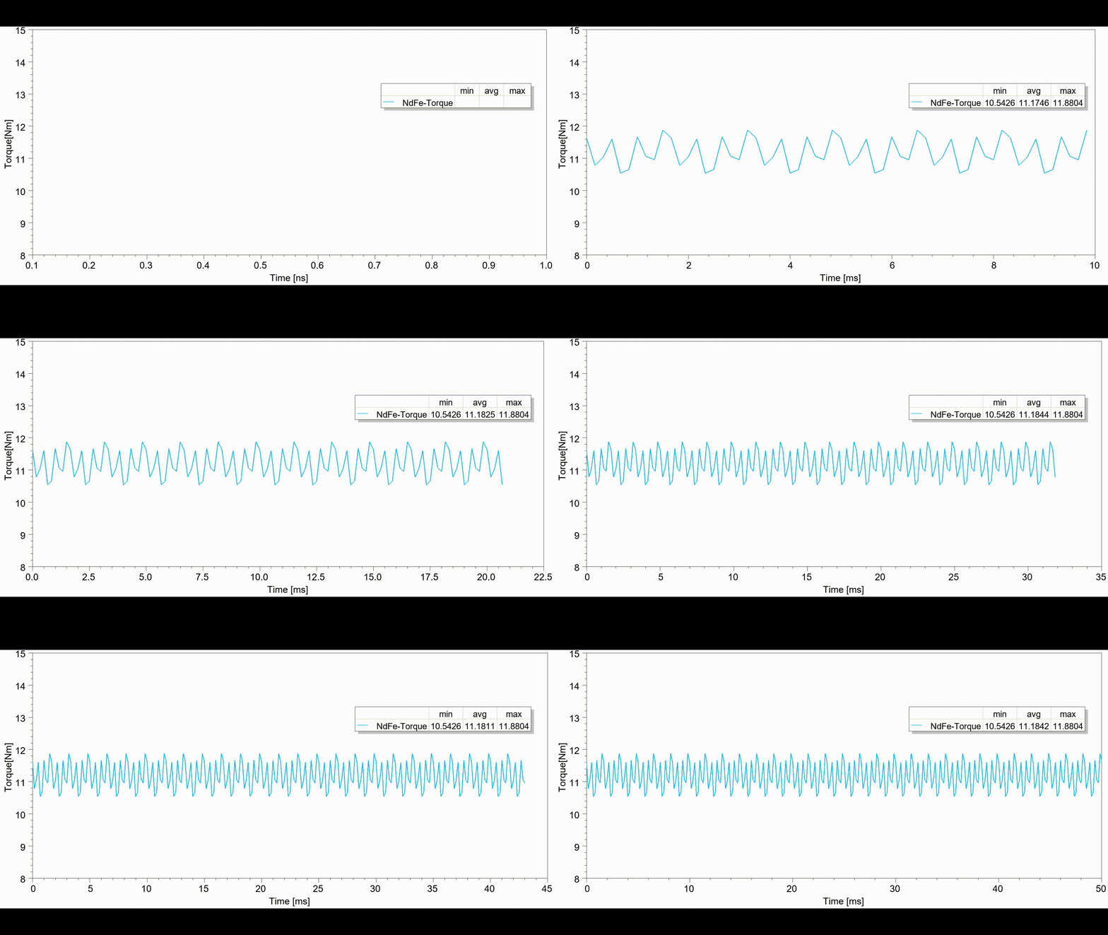
Let us take a reference design to evaluate the performance of these magnets in an electric motor. A four pole, 1.2 kW PMSM was designed for this study. With these magnets, the magnetic interaction generates approximately 11.18 Nm of torque at 3000 rpm for the designed motor.
We want to get rid of rare-earth magnets. Several alternative magnet types do not contain rare earth materials, such as ferrite, aluminum nickel cobalt (AlNiCo), and samarium-free composite magnets. These options are more affordable and easier to source, but their magnetic strength is significantly weaker compared to neodymium or dysprosium-based magnets. As a result, they cannot by themselves generate the same magnetic flux density or torque levels in an electric motor.
Why are rare-earth-free magnets unable to deliver the same performance?
When we examine the torque equation of an electric motor, two key factors stand out: the flux linkage produced by the rotor magnets and the current in the stator windings. When these are multiplied by the number of poles and other constants, they determine the torque. For a fixed current and motor design, only the magnet’s flux linkage directly influences the torque component.
Flux linkage represents the total magnetic flux that passes through the stator windings and is directly proportional to the magnetic strength of the rotor material, often described by its remanence. A higher remanence value means a stronger magnetic field and, therefore, greater flux linkage, which leads to higher torque production.
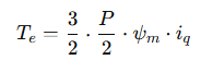
One of the most common rare-earth magnet grades, NdFeB N30, has a remanence of about 1.125 T at zero magnetic field strength. The resulting flux linkage depends on the magnet’s size and position.
Now, let’s consider an identical setup using a rare-earth-free ferrite magnet, such as Y33H, which has a remanence of 0.43 T. In theory, this means the torque output would be roughly 2.6 times lower for the ferrite magnet. However, this difference can be lower in practice due to demagnetization effects from the stator’s magnetic field. Ferrite magnets are generally more susceptible to demagnetization than NdFeB magnets, so the actual torque ratio is expected to be lower than 2.6.
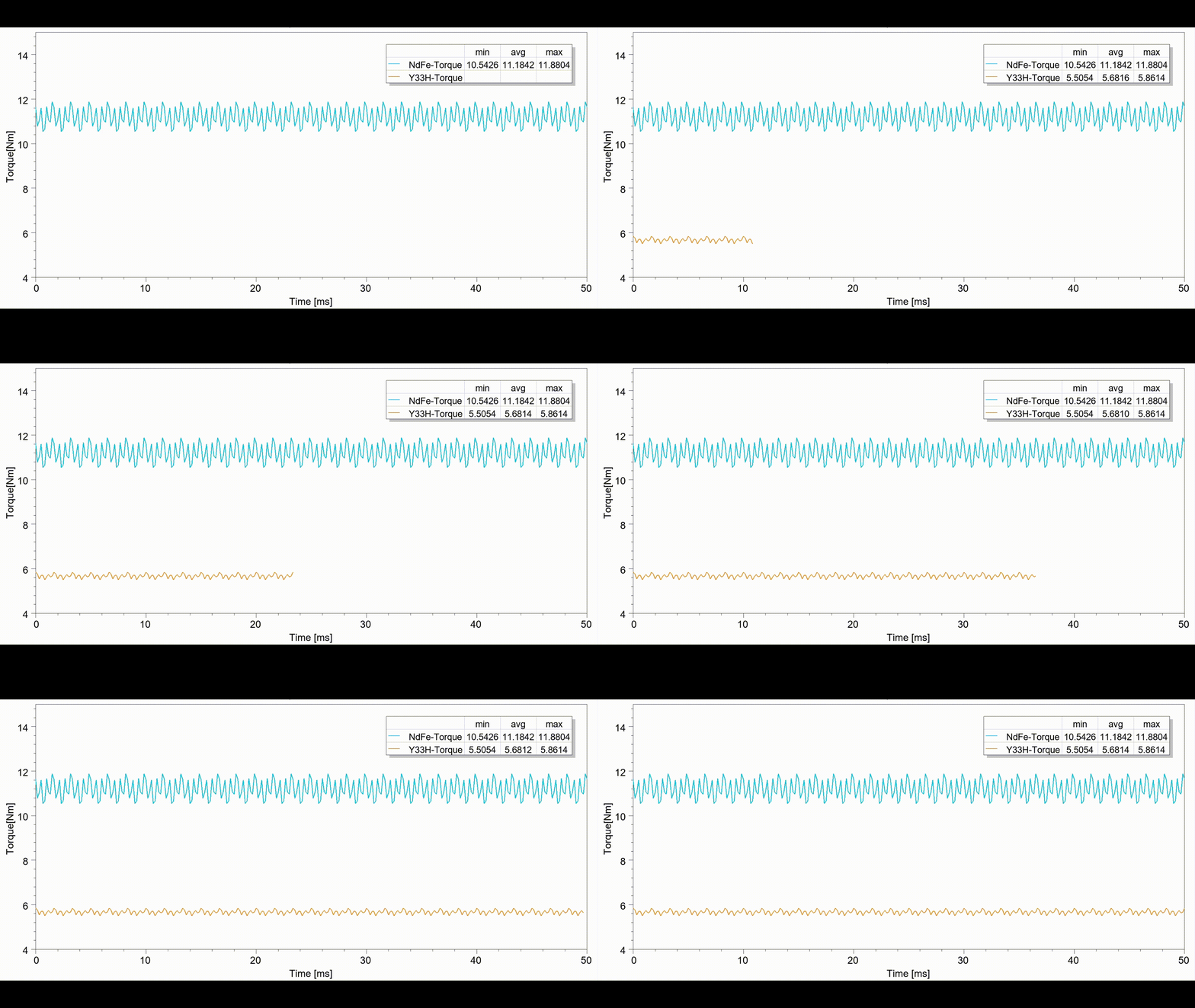
When we simulate the same motor using Y33H magnets, we observe that the ferrite version produces an average torque of 5.68 Nm, which is about half that of the NdFeB version.
So, this analysis shows that simply replacing NdFeB magnets with ferrite magnets does not solve the performance problem. That’s why we need to make use of the second torque component:
Reluctance Torque in Electric Motors
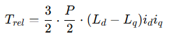
Most people have encountered this phenomenon at least once: when you suspend a small iron needle and move a magnet around it, the needle tends to align itself with the magnet. This occurs because the needle naturally seeks the path of least magnetic reluctance between the iron core and the magnetic field, and it creates a force on the needle. This effect is known as reluctance torque, and its magnitude depends on the difference in magnetic reluctance between the direct (d) and quadrature (q) axes of a structure. For an electric motor:
Here, two adjacent iron needles follow the rotating electromagnetic field in the stator, resulting in approximately 3 Nm of reluctance torque. However, as seen in the simulation, this torque is relatively low and noisy due to the current rotor shape. To achieve higher torque and lower noise, the rotor geometry must be redesigned to create a more optimized magnetic path.
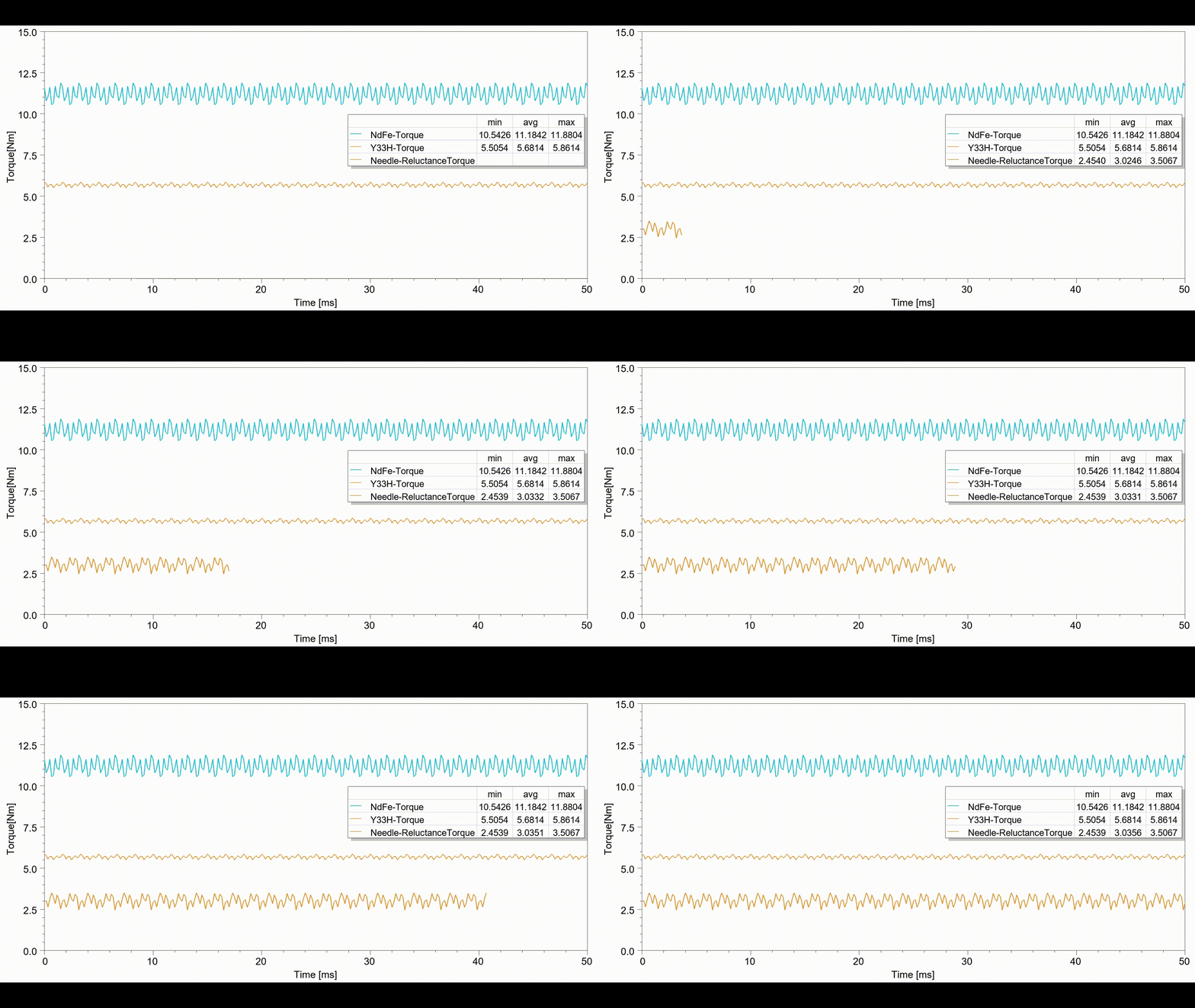
To reduce torque ripple and increase the torque output from the same motor, flux barriers—also known as air pockets—are introduced inside the rotor.
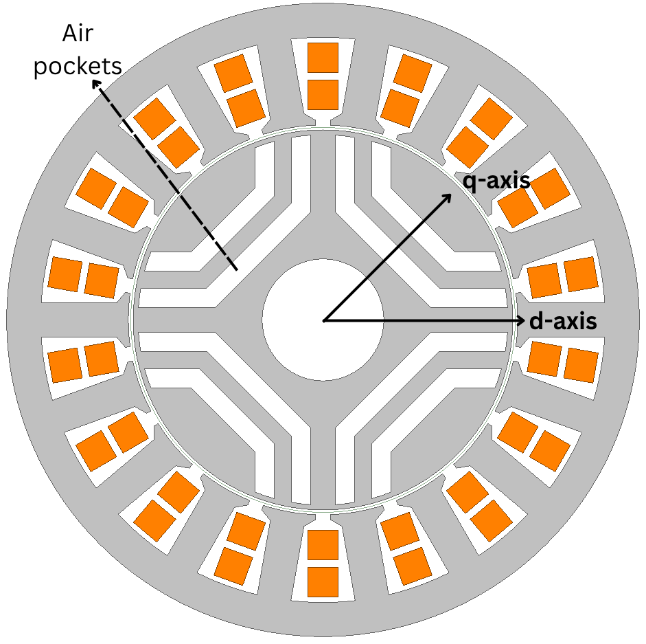
These air pockets create a magnetic reluctance difference between the d-axis and q-axis. In theory, having more or larger air pockets increases the reluctance torque, since the greater the difference in magnetic reluctance between the two axes, the higher the torque contribution. But more flux barriers may result in tight manufacturing tolerances between the barriers and the rotor outer edge.
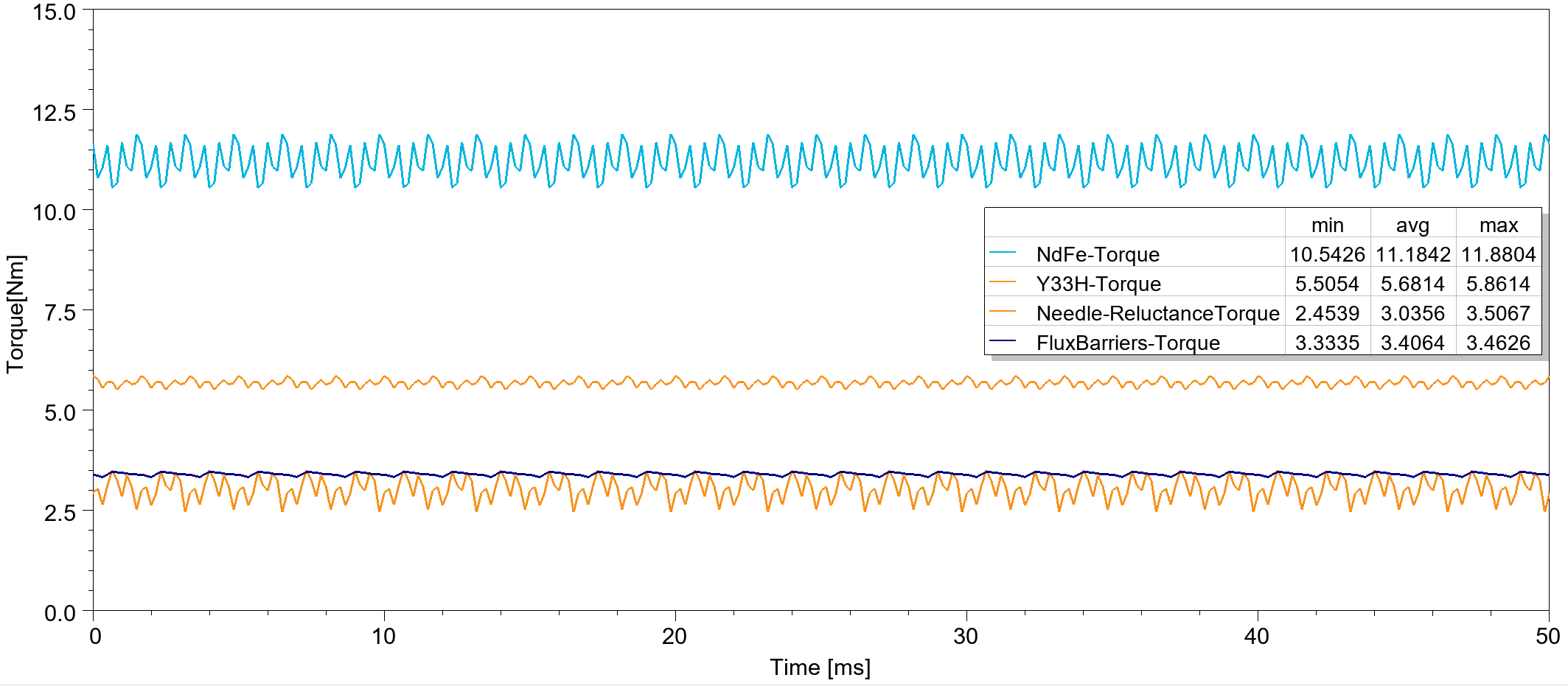
With this new rotor design, the motor operates with lower torque noise and delivers approximately 20% more torque.
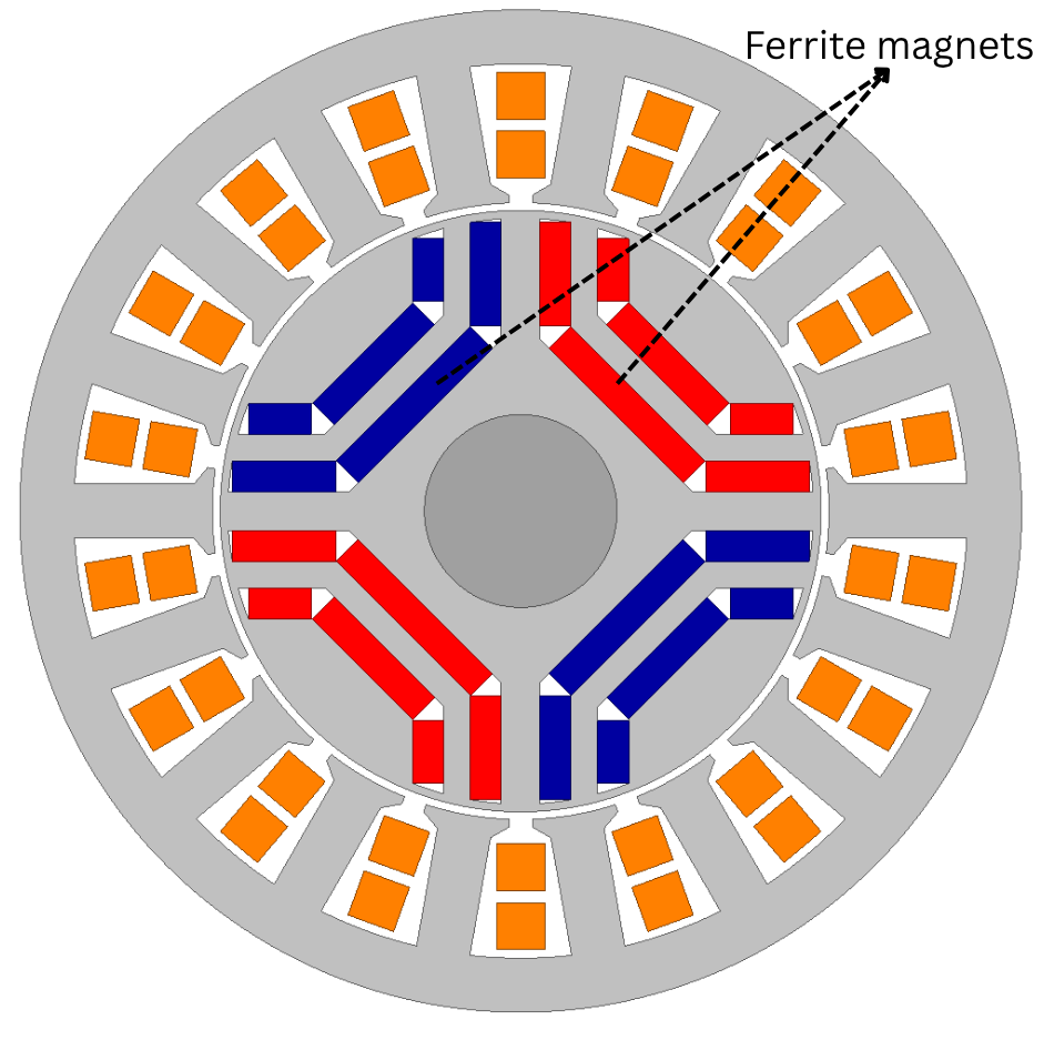
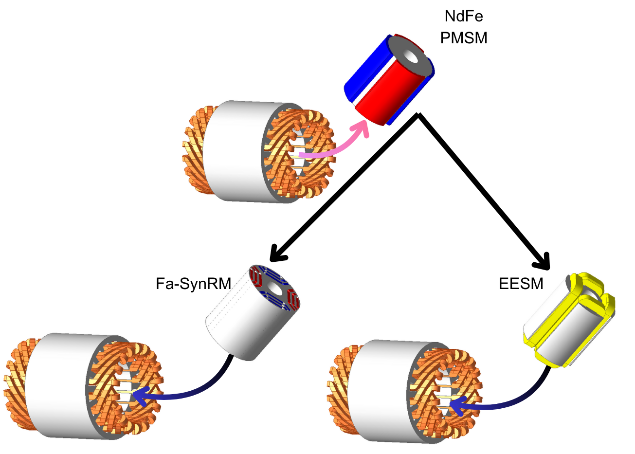
Now, the next question is: why not combine both torque components to achieve even higher performance? By placing rectangular ferrite magnets inside the flux barriers, we can form what’s known as a Ferrite-Assisted Synchronous Reluctance Motor (FaSynRM)—a design that merges the strengths of both reluctance and magnet torque.
With this configuration, the FaSynRM produces an average torque of 7.8 Nm. However, there is still a 3.38 Nm gap from NdFeB design. This gap represents the main bottleneck for the industry, as these magnets still cannot achieve the same performance as NdFeB designs.
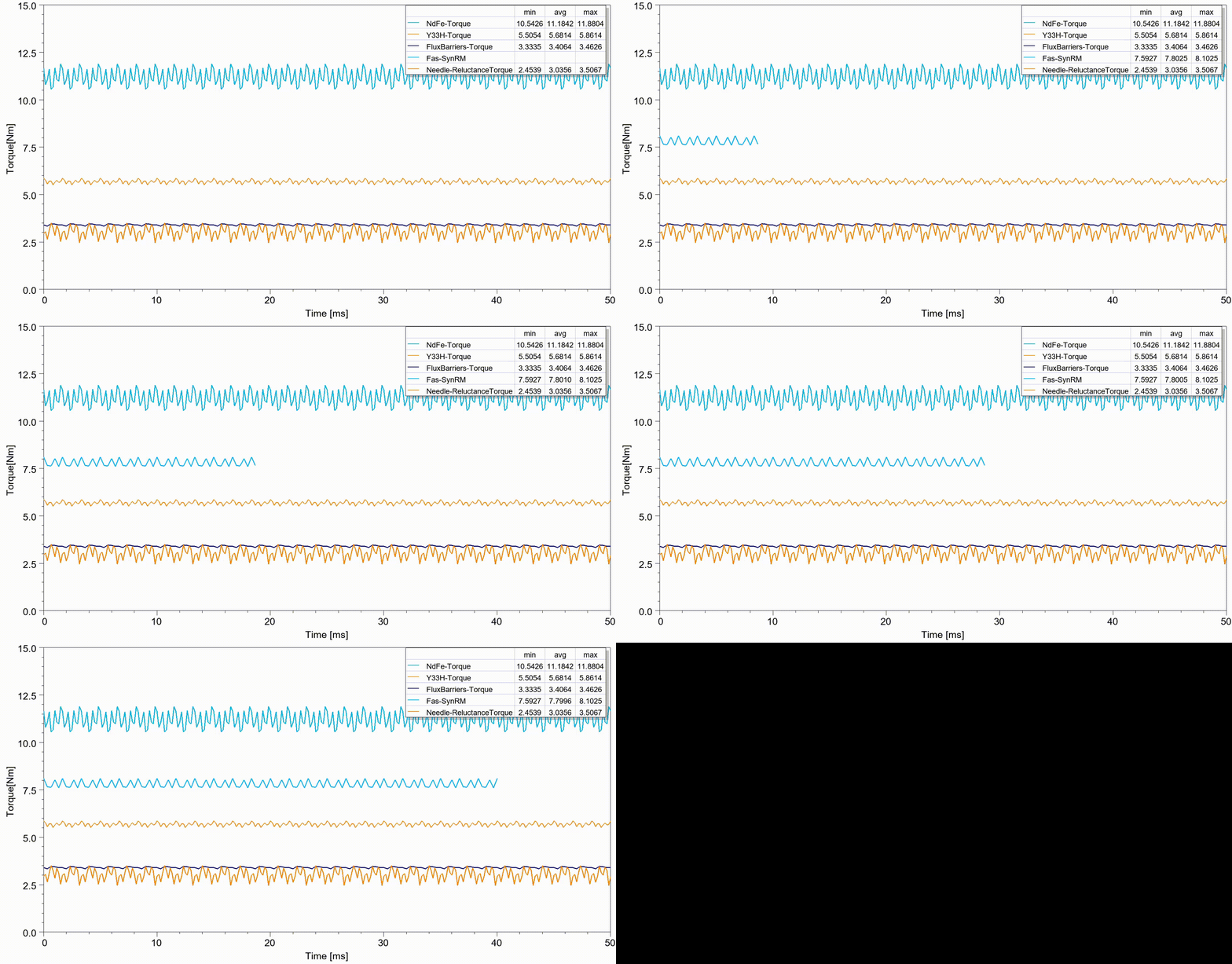
At this point, optimization becomes essential. Using Ansys optiSLang, we can refine the rotor geometry to reach 11.18 Nm of torque without changing the stator. In practice, users can simply replace their existing NdFeB rotors with optimized rare earth free rotors and maintain identical performance.
Optimizing Rare-Earth-Free Motors with Ansys
These motors need to be carefully optimized to reach their maximum performance potential. Every aspect of the motor geometry, from magnet size to even the smallest thickness variations in the rotor, must be precisely selected. By fine-tuning these details, both the reluctance torque and the magnet torque can be utilized at their peak, allowing the motor to deliver the highest possible efficiency and output without relying on rare earth materials.
So far, the results and simulations have been conducted in Ansys Maxwell, a general-purpose, high-fidelity electromagnetic simulation tool. However, Ansys also offers a more specialized tool for electric motor analysis called Motor-CAD. Motor-CAD provides template-based FEA solvers tailored for different types of electric motors. When coupled with optiSLang, using its user-friendly optimization interfaces, it becomes an ideal solution for optimizing the FaSynRM to achieve a target torque of 11.18 Nm.
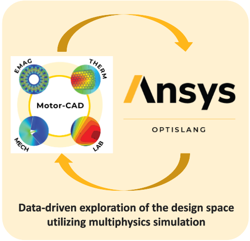
Ansy optiSLang performs multiple iterations within Motor-CAD, collects the results, and builds an optimization workflow using its internal algorithms. Based on these datasets, the tool generates an optimized electric motor design that meets the specified performance target — in this case, 11.18 Nm at 3000 rpm.
source: Ansys
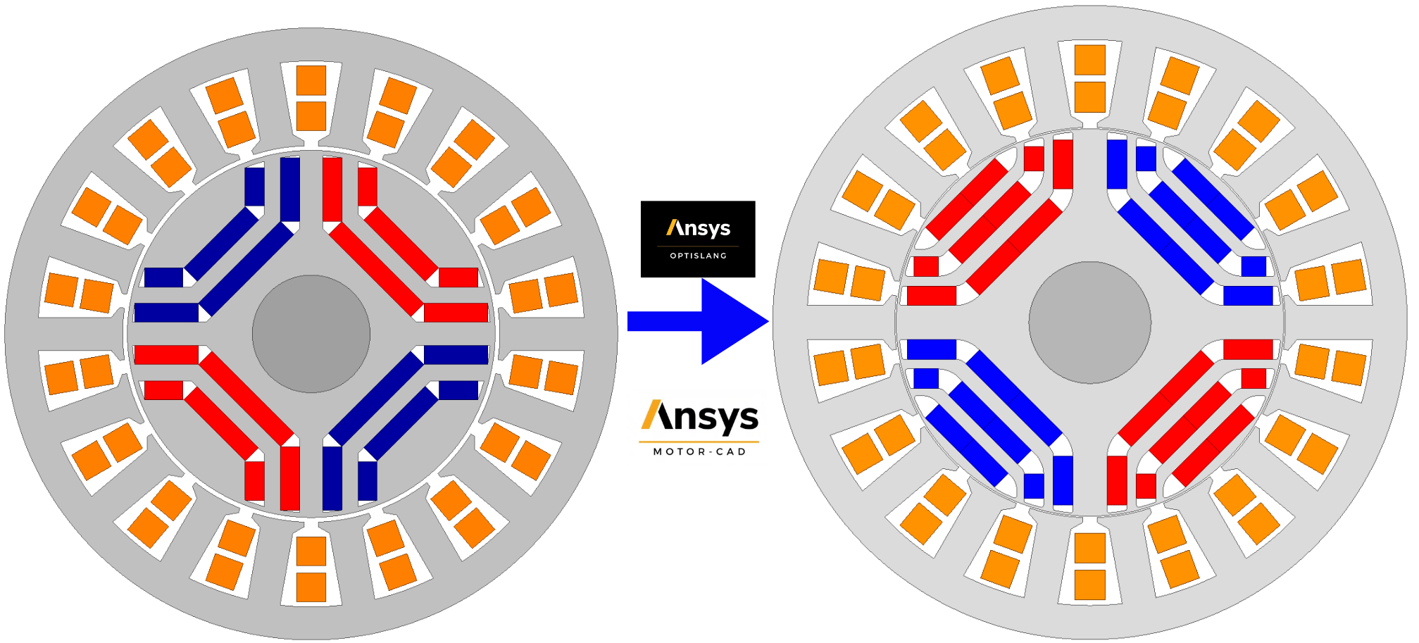
After optimizing the FaSynRM design in optiSLang through more than 500 FEA simulations and 10,000 analytical iterations, the motor was refined to deliver at least 11.18 Nm of torque at 3000 rpm.
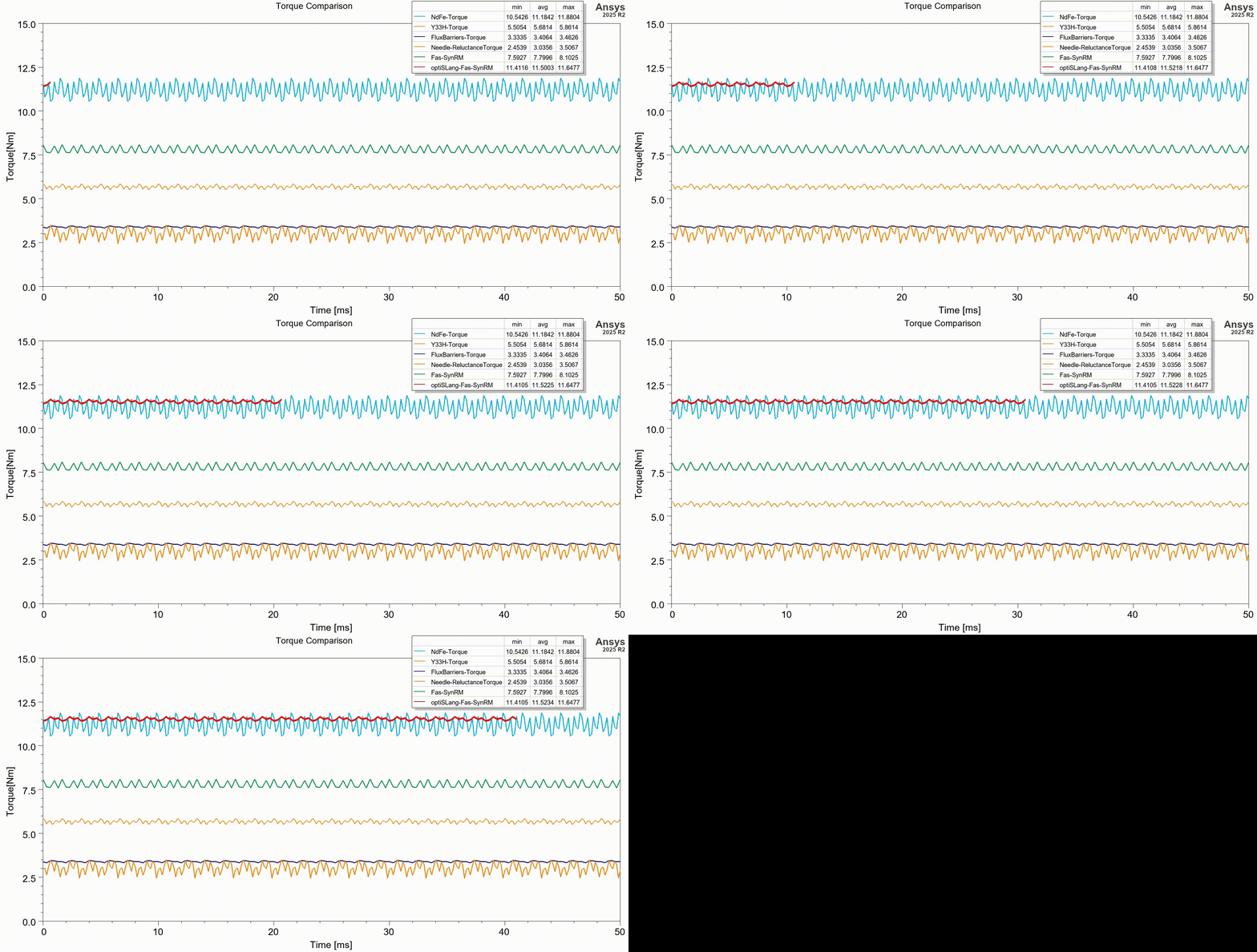
The same optimization workflow can also be applied to maximize efficiency or reduce torque ripple. In this rare-earth-free electric motors study, only the torque at 3000 rpm was optimized to achieve the same power level as the NdFeB design.
Magnet-Free Electric Motor Designs
For magnet-free motor types, the options to achieve the same torque density as NdFeB designs are limited. The two main candidates are Electrically Excited Synchronous Motors (EESM) and Induction Motors (IM). In this blog, we will focus on the EESM to highlight the potential growth of this motor type.
Induction motors, although relatively inexpensive and supported by a long history of mature manufacturing, may not directly replace the rotor of an NdFeB design without changing the outer diameter or axial length of the motor. This limitation arises because an induction motor relies on the Lorentz force to generate torque, and this torque is generally not sufficient to achieve the same torque and power density as synchronous motors. (N. Hashemnia and B. Asaei, “Comparative study of using different electric motors in the electric vehicles,” 2008 18th International Conference on Electrical Machines, Vilamoura, Portugal, 2008, pp. 1-5, doi: 10.1109/ICELMACH.2008.4800157.)
The EESM operates in a way similar to the PMSM. The main difference is that in the EESM, an external excitation source, which creates alignment torque with the stator’s rotating magnetic field, generates the magnetic field in the rotor. For this comparison, the stator dimensions are kept constant to achieve the goal of a direct rotor replacement between motor types.
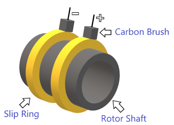
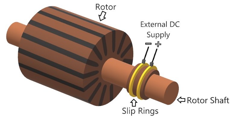
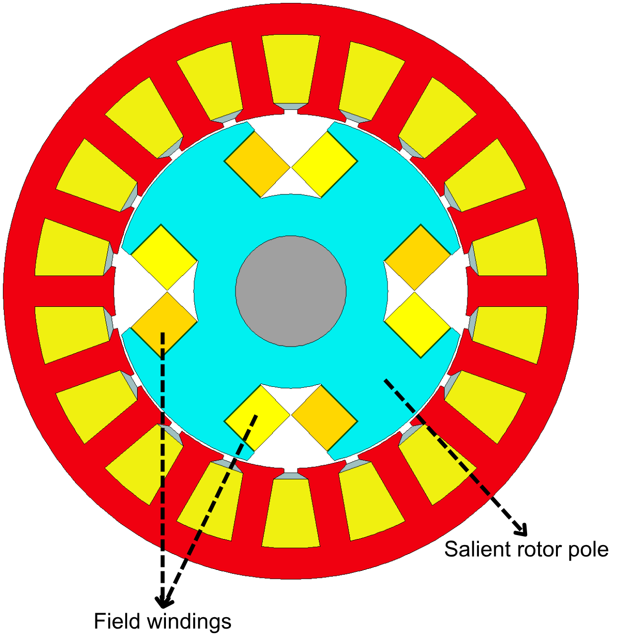 In an EESM, the electromagnetic field is generated using a pair of brushes and slip rings mounted on the shaft, which supply current to the winding coils around the rotor poles. The rotor topology in an EESM is quite different from that of a PMSM, as it must include slots to accommodate the wound coils. Two critical design factors are the number of turns that can fit within the rotor slots while respecting manufacturing tolerances, and the maximum current that can be supplied to these coils without overheating or damaging the motor.
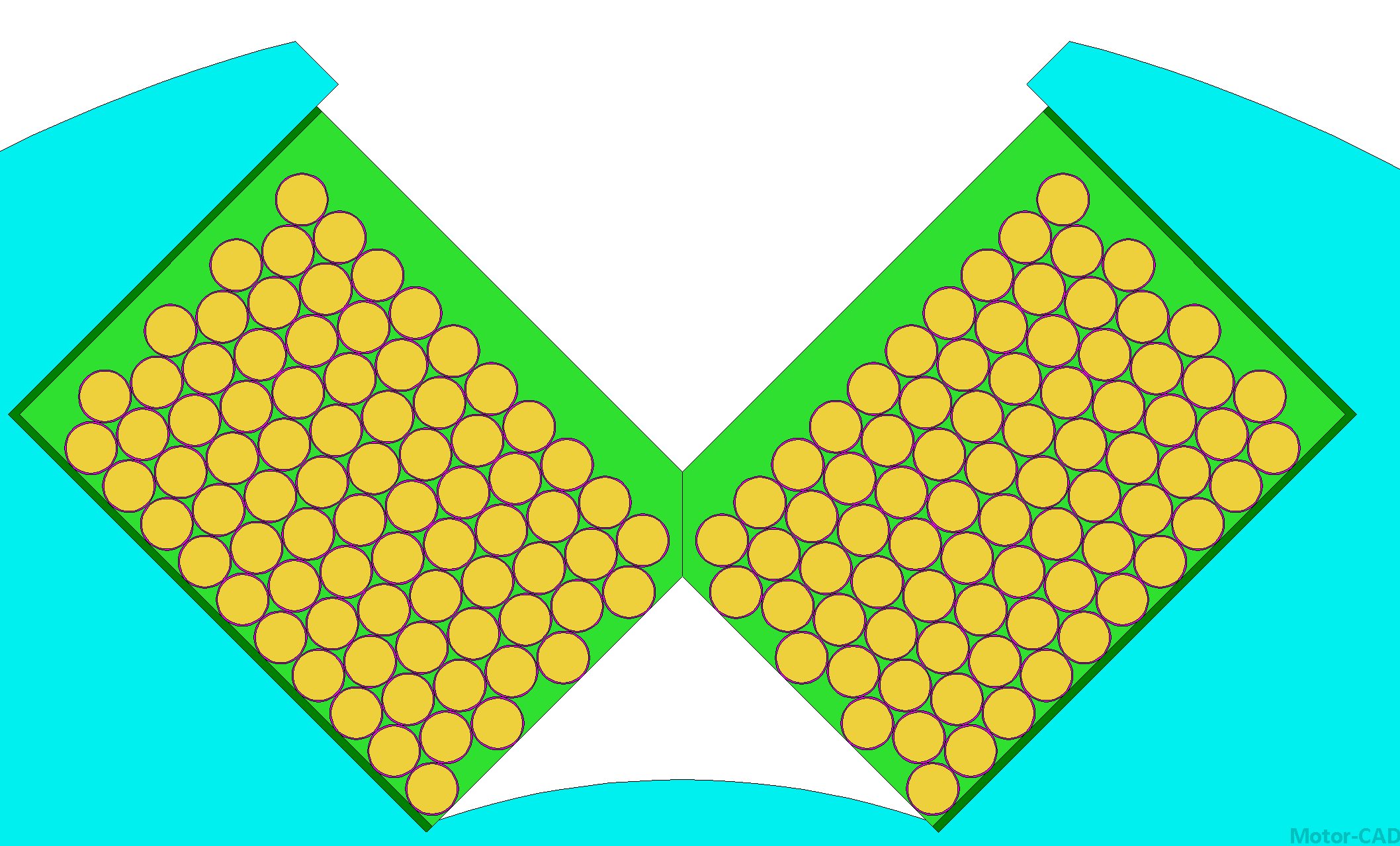
coil designs more quickly and efficiently.
In addition, with its built-in FEA solver, each winding in both the stator and rotor can be simulated using different cooling methods such as air fan, water jacket, or oil cooling. This allows to evaluate and refine the design to make it competitive with NdFeB PMSM systems.
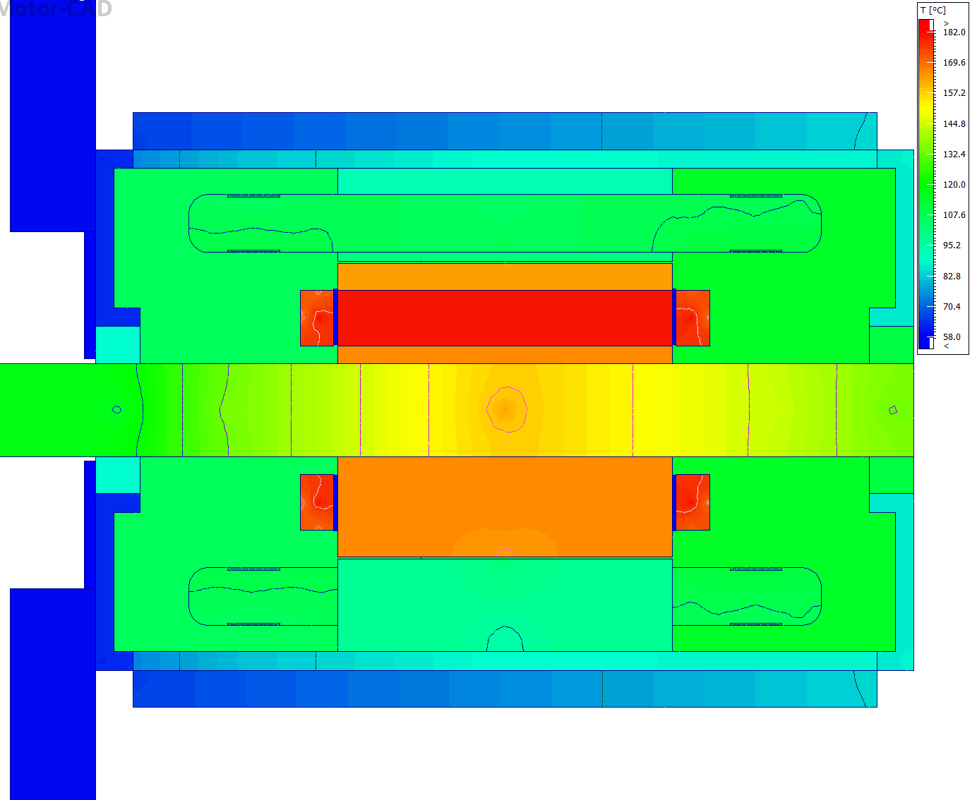
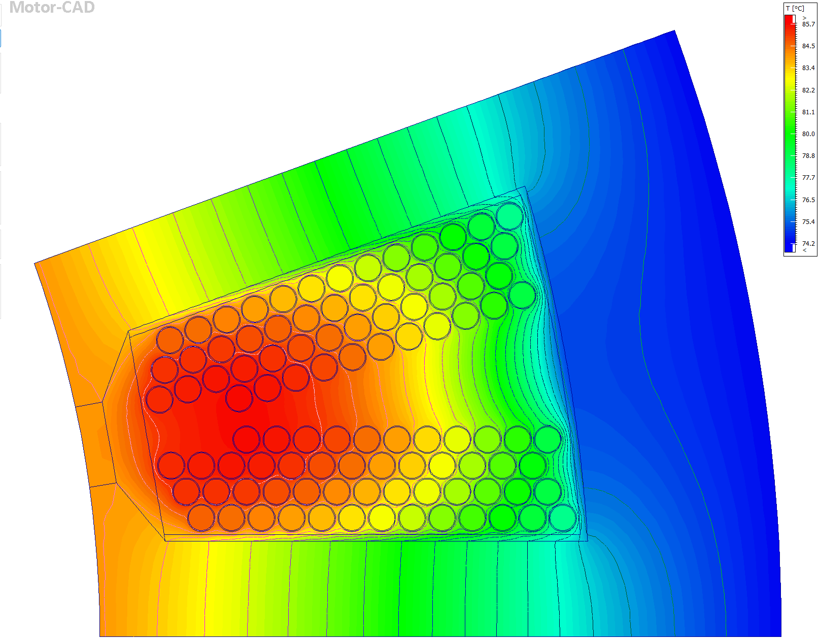
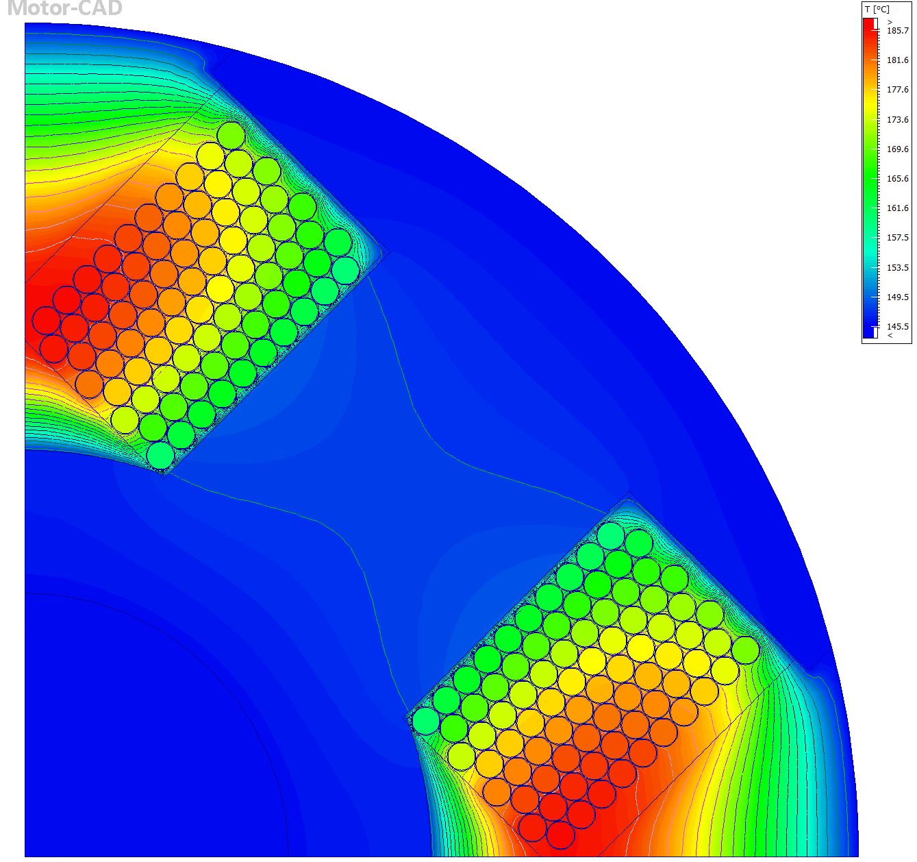
The main difference between an EESM and a PMSM is the presence of brushes and rings in the EESM. These components transfer direct current to the rotor windings through physical contact between the brushes and rings. Two rings — one positive and one negative — are mounted on the shaft, while two brushes (and in some cases more, to improve reliability) make contact with them. Although the brushes are designed to minimize friction and maintain smooth contact, and materials such as carbon are used to increase durability, these parts still require periodic maintenance. Typically, maintenance is needed every ten years, or up to twenty years with newer brush compositions, but they remain components that experience wear over time.
source: MunirAcademy
To overcome this limitation, new technologies in rare-earth-free electric motors now enable brushless DC excitation of the rotor windings (H. Chen, J. Tang, Y. Liu, B. Jiang and L. Boscaglia, “Electromagnetic Performance Investigation of a Brushless Electrically Excited Synchronous Machine for Long-Distance Heavy-Duty Electric Vehicles,” in IEEE Transactions on Transportation Electrification, vol. 11, no. 1, pp. 225-235, Feb. 2025). This approach simplifies manufacturing and improves reliability, although it still requires further development before it can be adopted for large scale production and long term operation. Depending on the application, modern brush and ring systems with extended lifespan can still be the more practical option when combined with proper optimization to maintain motor efficiency.
Comparing Rare-Earth-Free Motor Costs
Since the same stator, steel, and winding materials are used across all three designs, their costs remain identical. Although the rotor dimensions are the same, small variations in geometry create slight differences in rotor lamination costs.
As of today, N30 magnets cost approximately 60 USD per kilogram, while Y33 ferrite magnets cost about 1 USD per kilogram—making them roughly 60 times cheaper. Even though the FaSynRM design uses a larger magnet volume, its total magnet cost remains far below that of the NdFeB design. In EESM, AWG 16 is used for the rotor winding. It is priced at around 16 USD per kilogram.
When we calculate the active material costs in rare-earth-free electric motors, we find that the NdFeB magnets contribute about 30 percent of the total price of a PMSM. In contrast, the ferrite magnets cost only 0.64 USD, bringing the total FaSynRM motor cost to about 68.19 USD, which is 33 percent cheaper than the NdFeB design. The EESM, due to its additional rotor windings, is slightly more expensive than the FaSynRM but still about 20 percent cheaper than the NdFeB motor.
| NdFeB PMSM | Fas-SynRM | EESM | |
| Stator steel ( 6 $/kg) | 20.472 | 20.472 | 20.472 |
| Stator winding ( 16 $/kg) | 37.024 | 37.024 | 37.024 |
| Rotor steel ( 6 $/kg) | 13.896 | 10.05 | 9.6 |
| Rotor winding ( 16 $/kg) | – | – | 15.9136 |
| Rare-earth magnet ( 60 $/kg) | 31.536 | – | – |
| Rare-earth-free magnet ( 1 $/kg) | – | 0.6497 | – |
| Total ($) | 102.928 | 68.1957 | 83.0096 |
This cost analysis shows that, beyond solving supply chain issues associated with rare earth magnets, these alternative designs also significantly reduce production costs, making them far more budget-friendly for mass manufacturing. All these improvements are achieved simply by replacing the rotor of an existing motor with a rare-earth-free design with the correct optimization.
Advancing Rare-Earth-Free Electric Motor Design
Rare-earth-free electric motors offer manufacturers opportunities to reduce material costs and dependence on constrained supply chains while exploring alternative approaches to torque generation. Ferrite-assisted synchronous reluctance motors and electrically excited synchronous motors demonstrate how different rotor configurations can reduce or eliminate the need for rare-earth magnets.
Achieving competitive performance requires careful evaluation of electromagnetic behavior, rotor geometry, thermal management, and operating conditions. Ansys Maxwell, Motor-CAD, and optiSLang help engineers investigate these trade-offs and optimize designs against specific performance requirements.
SimuTech Group supports electric motor development through electromagnetic simulation, multiphysics analysis, and design optimization, helping engineering teams evaluate alternative motor technologies and make informed design decisions.