Contact Us
Stretch blow molding simulation in Polyflow lets engineers predict material distribution, wall thickness, and self-contact behavior before physical prototyping. This blog walks through a full injection stretch blow molding (ISBM) simulation setup in Ansys Fluent Polyflow, including a fractional factorial DOE comparing the effects of density, viscosity, stretch speed, and inflation pressure.
Design Challenges in Stretch Blow Molding
Designing for injection stretch blow molding (ISBM) presents several challenges due to the complexity of the process.
- Material distribution and wall thickness: During molding, the plastic is injected into a preform, then stretched and blown into the final shape. This requires precise control over how material flows to avoid weak points or inconsistencies.
- Part geometry: Sharp corners or intricate features are difficult to achieve without compromising structural integrity. The preform design is particularly important, as it dictates how the material will behave during stretching and blowing.
- Temperature control: The plastic must be at the right viscosity for proper stretch and blow. Too hot and the material may sag; too cool and it won’t stretch enough.
- Mold design and cooling: Cooling systems must be tuned to ensure uniform thickness and minimize defects. Variations in cooling rates can lead to warping or uneven wall thickness.
ISBM requires precise control over material flow, temperature, and part geometry to create strong, consistent, and aesthetically pleasing products.
Engineering Strategies for ISBM Process Improvement
To address the challenges of injection stretch blow molding (ISBM), engineers implement several key design strategies:
- Preform design: Focus on uniform wall thickness to ensure even material distribution during the blow molding process. Advanced simulation tools help predict how material will flow and stretch.
- Geometry refinement: Incorporate gradual radii and rounded corners to reduce stress concentrations and improve moldability. For complex designs, multiple-stage molds or advanced tooling may be used.
- Temperature management: Carefully manage the preform’s cooling rate for consistent stretching. Precise heating systems and advanced mold cooling channels prevent warping and ensure uniform wall thickness.
- Material selection: Using resins with the right balance of flow and strength properties helps achieve the best results. Additives can improve stretchability and reduce defects.
- Mold design: Multi-cavity molds with precise control over cooling and air pressure ensure high-quality, consistent parts. Automation is often employed to speed production and reduce cycle times.
Why Ansys Fluent Polyflow Is Built for Stretch Blow Molding Simulation
ANSYS Fluent Polyflow is a powerful simulation tool for addressing engineering challenges in injection stretch blow molding (ISBM). It enables engineers to model the complex fluid dynamics of polymer flow during the injection, stretching, and blowing phases, providing insights into material behavior and part performance. Polyflow simulates the injection process, predicting the material distribution within the preform and identifying areas of uneven thickness or stress concentrations that could lead to defects such as warping or weakness.
For the stretching and blowing phases, Polyflow simulates how the preform material deforms under mechanical stretching and pressure during blowing, allowing engineers to optimize preform geometry and mold design. This helps ensure uniform wall thickness and structural integrity in the final product.
Polyflow also facilitates temperature and cooling simulations, ensuring the preform is heated to the optimal viscosity for blowing. By simulating thermal gradients, engineers can adjust cooling rates and mold design to prevent issues such as warping and inconsistent thickness.
Simulation Setup: Thought Map, Product Map, and Polyflow Configuration
Setting up Injection Stretch Blow Molding with Ansys Fluent-Polyflow involves several steps. These steps include the thought map, product map, and Polyflow case setup.
Thought Map
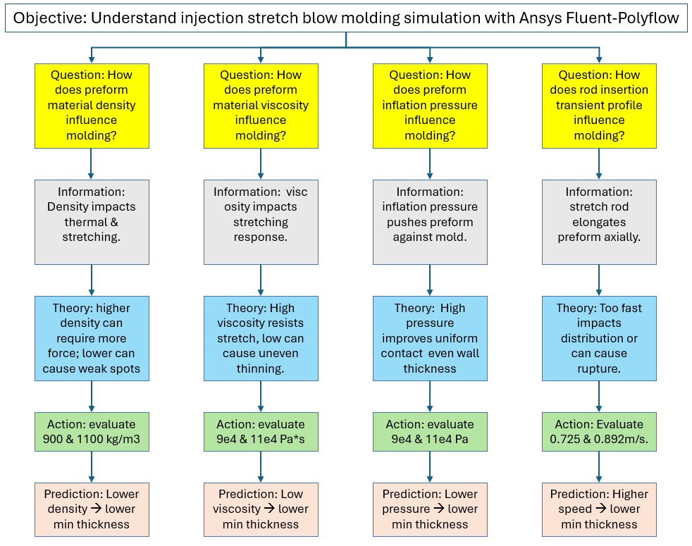
A thought map of the blow molding characteristics is generated to organize and represent ideas, concepts, or information in a structured way. The thought map below shows the simulation study’s objective and the questions asked to address it. Each question is followed by a theory, an action, and a prediction. Results would also be added to the bottom of each branch as they are generated.
Product Map
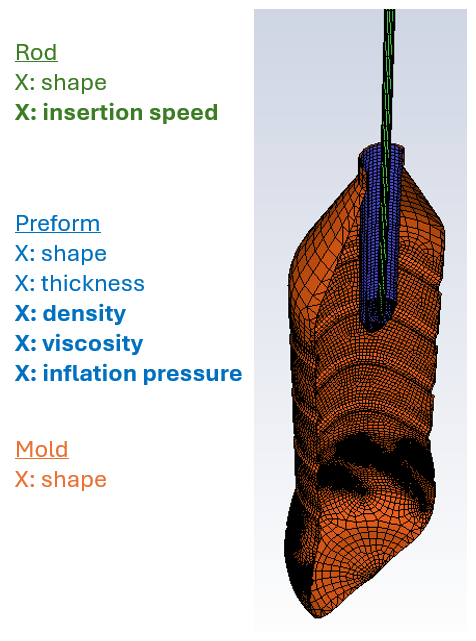
A product map of the blow molding preform, mold, and rod is generated to list and categorize product features. A product map indicates factors that correspond to theories/actions in the thought map.
Polyflow Simulation Setup
Polyflow models are generated per the studies produced by the thought map. In this case, a fractional factorial DOE is employed, yielding unique Polyflow treatments. The images below show the sequence of steps for populating inputs for a Polyflow model.
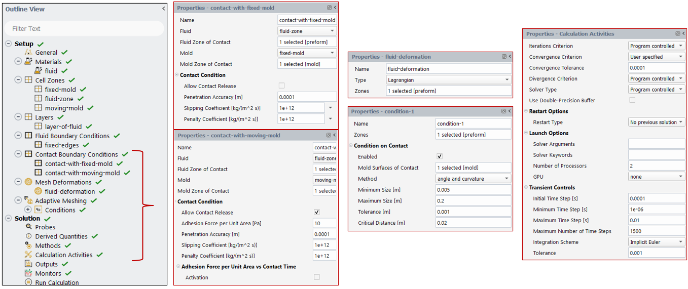
The motion of the rod and the inflation pressure are both defined using expressions.
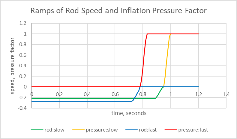
The simulation calculations are performed to generate the results, with a focus on thickness and overlap. The treatment data are analyzed to answer theoretical questions and to confirm or refute predictions.
Stretch Blow Molding Simulation Results: DOE Factor Analysis
Graphical Analysis
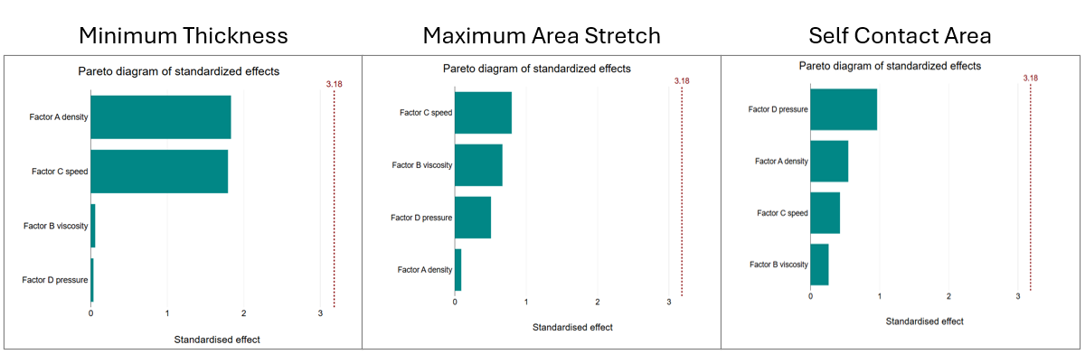
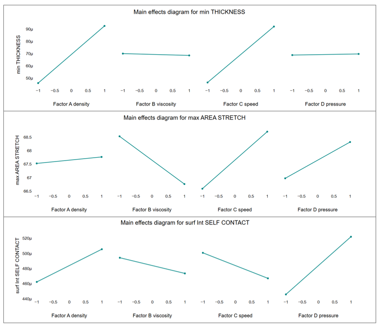
The charts below display the results for the treatments. The charts indicate that the input factors have a small impact on the output metrics. The fluid density and stretch speed have a greater influence on the minimum thickness than the viscosity and pressure. The density has less impact on the maximum area stretch than the other three factors. The inflation pressure has a slightly more impact than the other three factors.
Increasing the fluid density tends to increase the minimum thickness and to increase the area of self-contact.
Increasing the viscosity tends to decrease the maximum area stretch and the area of self-contact.
Increasing the stretch speed tends to increase the minimum thickness, increase the maximum area stretch, and decrease the area of self-contact.
Increasing the inflation pressure tends. to increase the maximum area stretch and increase the area of self-contact.
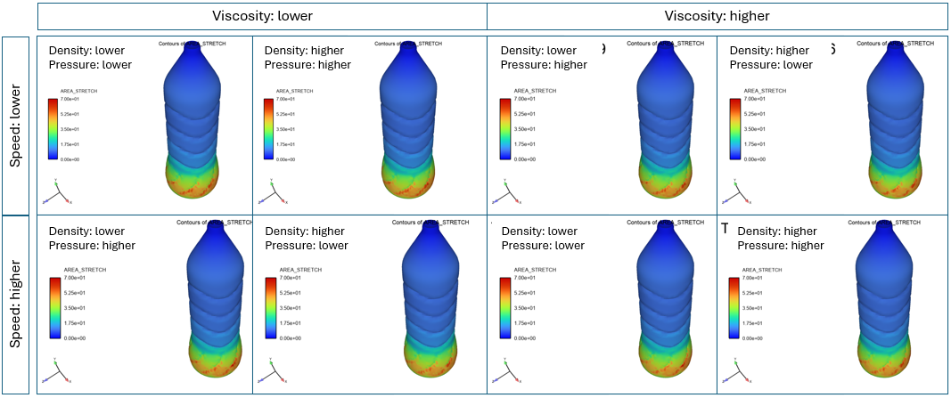
The contour plots below show the small variation in area stretch among the eight treatments.
The animation below shows the process of rod motion and inflation.
{% video_player “embed_player” overrideable=False, type=’hsvideo2′, hide_playlist=True, viral_sharing=False, embed_button=False, autoplay=False, hidden_controls=False, loop=False, muted=False, full_width=False, width=’1068′, height=’652′, player_id=’190030269300′, style=” %}
The following video highlights the setup.
Benefits of Ansys Fluent Polyflow for Blow Molding Process Design
Ansys offers advanced capabilities for simulating Injection Stretch Blow Molding, which offer numerous benefits, including enhanced design optimization, improved reliability, and cost savings. By accurately predicting blow molding performance, manufacturers can design products that meet specific requirements more efficiently.
Ultimately, Ansys Fluent Polyflow provides a comprehensive virtual environment for fine-tuning material behavior, mold design, and process parameters, leading to more efficient production, reduced trial-and-error, and improved part quality in ISBM processes.
Ansys Fluent-Polyflow enables the evaluation of multiple design/input factors such as density, viscosity, stretch speed, and inflation pressure. A manufacturing engineer can evaluate multiple design options to understand the molding behavior. Beyond Polyflow, Ansys provides tools such as LS-Dyna, DesignXplorer, OptiSLang, and Mechanical for further design parametrization and evaluation.
Working on blow molding, ISBM, or polymer processing simulation? SimuTech Group’s CFD consulting engineers work with Ansys Fluent Polyflow and the full material processing simulation suite. For more on Polyflow manufacturing simulation, see our article on thermoforming simulation in Ansys Fluent Polyflow. Learn more about Ansys Fluent or contact us to discuss your project.