Contact Us
Introduction to Ansys Forte Fluid Machinery Simulation
Mention Ansys Forte in a room full of CFD engineers, and the conversation will likely turn to internal combustion engines, fuel injection, and combustion chemistry. While Forte remains one of the industry’s leading engine simulation platforms, its underlying technology extends well beyond combustion applications. Today, engineers are increasingly leveraging Forte to analyze lobe pumps, screw compressors, gerotor pumps, hydraulic devices, and other forms of complex fluid machinery that involve moving boundaries and continuously changing fluid domains.
As industries continue to push for greater efficiency, reliability, and shorter development cycles, engineers are adopting Forte not only for combustion analysis but also for the virtual prototyping and optimization of complex fluid machinery. Its ability to capture transient flow behavior, moving components, and built-in fluid-structure interaction (FSI) effects allow engineers to gain deeper insight into machine performance before physical prototypes are built.
As part of the Ansys ecosystem, Forte benefits from an integrated workflow that spans geometry preparation, simulation, design exploration, optimization, and emerging AI-driven engineering tools. This connectivity allows organizations to accelerate product development while gaining deeper insight into some of the most challenging fluid machinery applications in modern engineering.
Ideal Applications for Ansys Forte
Although Ansys Forte is best known for combustion simulation, its capabilities extend across a diverse range of fluid machinery applications. As shown in Figure 1, Forte can be applied to systems ranging from piston engines and compressors to pumps and fluid-structure interaction (FSI) problems. Despite their differences, these applications share common characteristics, including moving boundaries, changing fluid volumes, transient flow behavior, leakage paths, and strong interactions between fluid and mechanical components.
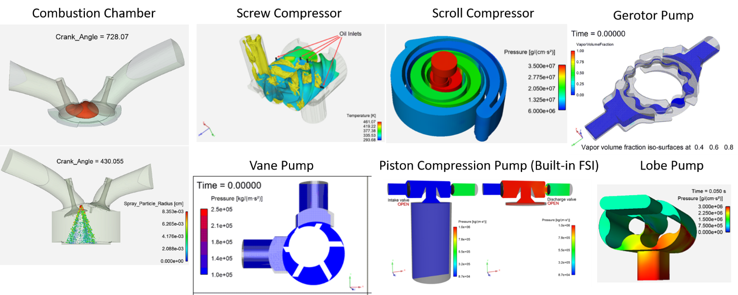
The common thread among these applications is the presence of moving boundaries, changing control volumes, leakage paths, transient flow phenomena, and, in some cases, fluid-structure interactions. These challenges make them particularly well suited to Forte’s automated meshing, built-in physics models, and transient simulation capabilities.
Piston Engines and Combustion Systems
Internal combustion engines remain one of Ansys Forte’s most widely adopted applications. Engineers use Forte to investigate in-cylinder flow motion, fuel injection, air-fuel mixing, combustion efficiency, emissions formation, and heat transfer. Its ability to accurately capture piston and valve motion, together with advanced combustion models, makes it a powerful tool for virtual engine development and calibration.
Compressors
Beyond combustion, Forte is well suited for positive-displacement compressors that involve rapidly changing chamber volumes and complex leakage paths.
Screw Compressors
Twin-screw compressors present challenges associated with rotor interaction, internal leakage, and compression heating. Forte enables engineers to evaluate pressure development, leakage flows, thermal effects, and overall compressor efficiency throughout the compression cycle.
Scroll Compressors
Scroll compressors contain continuously evolving enclosed chambers that are often difficult to model using conventional CFD techniques. Forte can capture chamber evolution, flow distribution, pressure buildup, and leakage mechanisms, providing valuable insight into compressor performance and design optimization.
Gerotor Pumps
Widely used in lubrication and hydraulic systems, gerotor pumps contain rapidly changing chambers and tight clearances that strongly influence performance. Forte enables detailed analysis of pressure development, flow ripple, cavitation tendencies, and volumetric efficiency.
Vane Pumps
For vane pump applications, simulation can be used to investigate pressure pulsations, chamber filling characteristics, internal leakage, and overall pumping performance across different operating conditions.
Piston Compression Pumps
In piston compression pumps, valve motion and fluid dynamics are strongly coupled. Forte’s built-in FSI capabilities allow valve behavior to be predicted directly from fluid forces, enabling more realistic simulation of pressure development, flow rates, and overall system performance.
Lobe Pumps
Lobe pumps are commonly used where gentle fluid handling is required. Forte helps engineers evaluate flow distribution, chamber filling, leakage paths, pressure pulsations, and volumetric efficiency, enabling improved designs before physical prototypes are built.
Detailed Application Example: Lobe Pump Analysis
Within Ansys Forte fluid machinery simulation, lobe pumps provide an excellent example of the software’s ability to handle complex moving geometries and transient flow behavior.
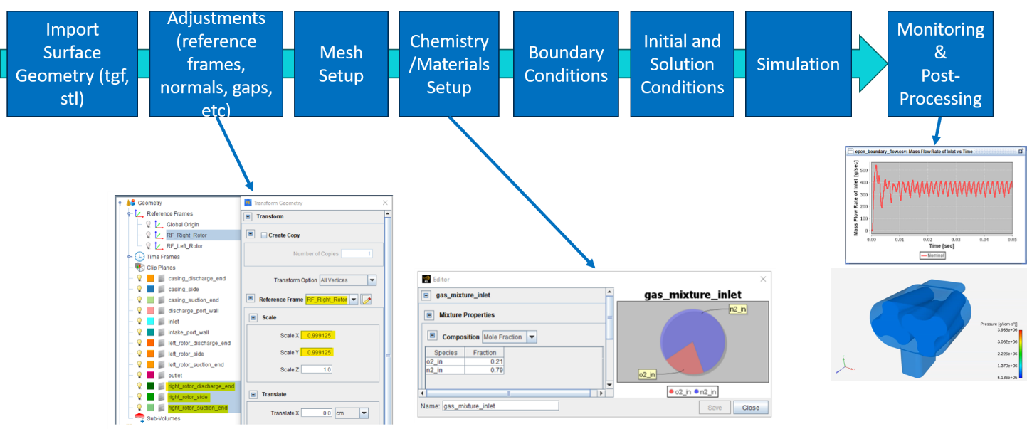
The workflow used to develop a lobe pump simulation in Forte is shown in Figure 2. Starting from the imported CAD geometry, the model is prepared through mesh definition, physics setup, boundary condition specification, and solution initialization before executing the transient simulation.
Geometry and Motion Definition
The rotary lobe pump considered in this study consists of two synchronized lobes rotating within a stationary housing. As the lobes rotate, a series of enclosed chambers transport fluid from the inlet to the outlet while maintaining tight clearances between moving and stationary components.
For this analysis, the CAD model was first created in Ansys Discovery and exported in TGF format for import into Ansys Forte. Once imported, reference frames and component motions were defined to accurately represent the lobe rotation and the evolution of the fluid domain throughout the pumping cycle.
Automatic Mesh Generation
One of Forte’s distinguishing features is its Automatic Mesh Generation (AMG) capability. Unlike conventional CFD workflows that require the creation of a body-fitted volume mesh prior to simulation, Forte only requires the imported surface geometry as input. The computational mesh is generated automatically and continuously updated throughout the simulation as the moving components evolve.
The AMG process begins by defining a material point, which identifies the fluid region to be meshed. This point must remain within the fluid domain throughout the simulation and serves as a reference for the automatic creation of the computational mesh. Once the fluid region is established, mesh resolution is controlled through a global mesh size that serves as the baseline cell size for the domain.
Additional refinement controls can then be applied to improve resolution in areas of interest. Common controls include surface refinement for capturing geometric details, gap refinement for resolving narrow clearances between moving components, and Solution Adaptive Mesh (SAM) refinement, which dynamically increases mesh resolution in regions where additional accuracy is required.
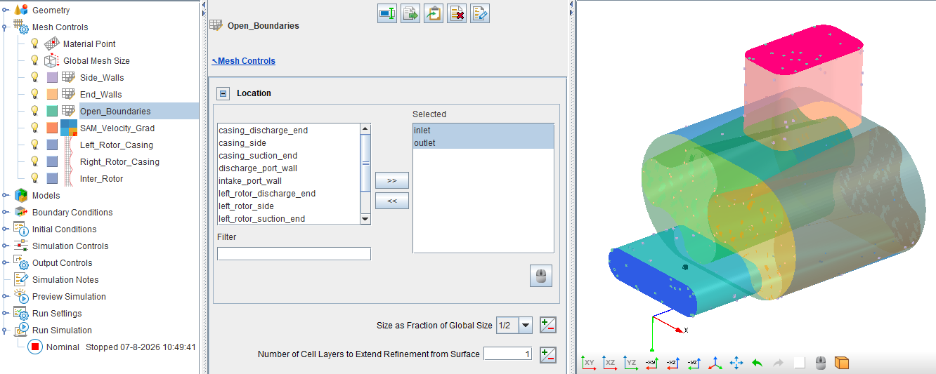
Figure 3 shows a typical mesh control setup for the lobe pump simulation. The inlet and outlet boundaries receive additional refinement with a cell size equal to one-half of the global mesh size (which is 0.4 cm for this case), while adaptive and local mesh controls are used to resolve important flow features throughout the domain.
Boundary Conditions and Fluid Definition
After the mesh controls are established, the next step is defining the boundary conditions and working fluid properties. For this lobe pump example, the inlet and outlet boundaries are assigned pressure boundary conditions corresponding to the pump operating conditions.
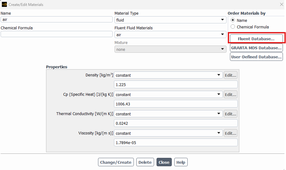
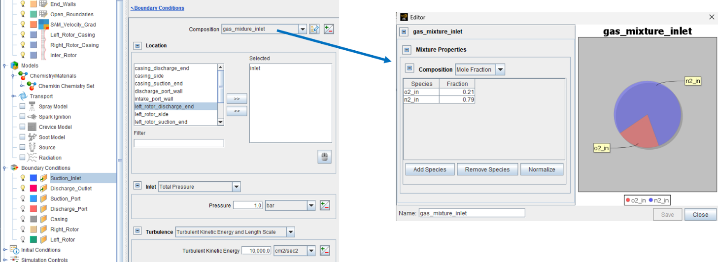
Unlike many conventional CFD tools that simply require a fluid material selection, Forte requires the user to define a gas mixture composition that describes the fluid entering the domain. The composition is created within the Chemistry/Materials framework and can consist of one or more species defined using mole or mass fractions.
For this Ansys Forte fluid machinery simulation example, the inlet mixture represents air and is defined using oxygen and nitrogen species with mole fractions of approximately 21% O₂ and 79% N₂, as shown in Figure 4. Once the mixture is created, it can be assigned directly to the inlet boundary condition through the Composition field.
Initial and Solution Controls
Once the geometry, mesh controls, fluid properties, and boundary conditions have been defined, the simulation is initialized by specifying the starting thermodynamic state of the fluid domain. Similar to the inlet boundary condition, Forte allows users to define a gas mixture for the initial conditions independently from the inlet and outlet gas mixtures. This provides flexibility for applications in which the fluid initially present in the domain differs from the fluid entering or leaving the system during operation. In many cases, including the present lobe pump example, the initialization mixture is identical to the inlet mixture and consists of air represented by oxygen and nitrogen species.
This initialization mixture establishes the fluid composition, pressure, and temperature present throughout the domain at the start of the simulation.
Solution controls are then used to specify the simulation duration, time-step strategy, output frequency, and convergence criteria. Because the lobe pump contains continuously evolving chambers and moving boundaries, a transient solution approach is required to accurately capture chamber filling and emptying, pressure development, leakage flows, and flow pulsations throughout the pumping cycle.
Monitoring and Output Controls
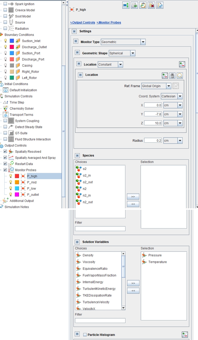
Before launching the simulation, users can define Output Controls to monitor key quantities of interest throughout the solution process. These controls allow important performance metrics to be tracked in real time and saved for post-processing, such as temperatures, pressures, and velocities.
In this example, several pressure monitoring locations were defined within the pump to track the transient evolution of pressure throughout the pumping cycle. These probes enable the evaluation of chamber filling and emptying, pressure pulsations, and pressure buildup between the suction and discharge ports.
Figure 5 is an example of an output control setup showing pressure monitoring locations within the lobe pump model. The monitored pressure signals can be tracked during the simulation and subsequently analyzed to evaluate transient pump behavior and performance.
The resulting pressure histories provide a convenient way to assess solution stability and determine when the simulation has reached a periodic operating condition. In addition, the monitored data can be used to quantify pressure ripple, characterize flow pulsations, and compare the performance of alternative pump designs.
This monitoring capability allows engineers to move beyond visualizing flow fields and directly evaluate performance metrics that are often measured during physical testing.
Post-Processing and Visualization
Once the simulation is complete, the results can be analyzed using either Ansys EnSight or Ansys CFD-Post, depending on the desired level of visualization and analysis.
Ansys EnSight is particularly well suited for large transient datasets and advanced animations. Engineers can create high-quality visualizations of pressure, velocity, vorticity, particle traces, and moving fluid domains, making it an excellent tool for understanding complex flow behavior and communicating results.
Ansys CFD-Post provides a familiar environment for quantitative analysis and reporting. Users can generate contour plots, streamlines, XY plots, performance curves, and derived quantities such as pressure drop, flow rate, and volumetric efficiency. CFD-Post also offers powerful tools for comparing operating conditions and extracting engineering metrics from the simulation results.
Conclusion
Although Ansys Forte is best known for its combustion simulation heritage, its capabilities extend far beyond piston engines. As demonstrated by the wide range of applications shown in Figure 1, Forte provides a powerful simulation environment for compressors, pumps, fluid-structure interaction problems, and other fluid machinery characterized by moving boundaries and continuously evolving fluid domains.
The lobe pump example presented in this article highlights how engineers can leverage Forte’s automated mesh generation, flexible boundary condition framework, built-in physics models, and integrated post-processing capabilities to efficiently simulate complex positive-displacement machinery. From geometry import and motion definition to transient flow visualization and performance evaluation, the workflow allows users to focus on understanding the physics rather than managing mesh updates and model complexity.
As part of the Ansys ecosystem, Forte also benefits from seamless integration with geometry creation, design exploration, optimization, and emerging AI-driven engineering workflows. This connectivity enables organizations to accelerate product development while gaining deeper insight into machine performance, reliability, and efficiency.
Whether the objective is analyzing combustion, evaluating a screw compressor, optimizing a gerotor pump, or understanding flow behavior within a lobe pump, Ansys Forte provides a robust and versatile platform for tackling some of the most challenging fluid machinery simulations in modern engineering. Ultimately, its value lies not only in the physics it can solve, but also in the engineering decisions it helps inform.
Additional Resources
The following video provides a detailed walkthrough of the lobe pump example featured in this article on Ansys Forte fluid machinery simulation, including geometry and motion setup, automatic mesh generation, boundary conditions, fluid definition, transient solution controls, pressure monitoring, and post-processing of the Ansys Forte simulation results.
Simulate Complex Fluid Machinery with Ansys Forte
See how SimuTech can help you apply Ansys Forte to pumps, compressors, moving-boundary systems, and other challenging transient CFD applications.

Ertan Taskin, Ph.D., Chemical Engineering
Principal Engineer, SimuTech Group
Ertan is a Principal Engineer with more than two decades of experience in CFD, fluid-structure interaction, and biomedical device design. He has advanced ventricular assist devices, transcatheter heart valves, and artificial lungs through hydraulic optimization, in vitro validation, predictive modeling, and AI-driven data analysis. His recent work integrates machine learning for performance prediction and design optimization. His career includes senior engineering roles at Medtronic, HeartWare, Roketsan, and Ozen Engineering, where he led projects spanning medical devices and aerospace propulsion. Ertan’s expertise includes blood damage modeling, uncertainty quantification, integrated thermo-fluid systems, and AI-assisted simulation workflows. He holds a Ph.D. in Chemical Engineering from Worcester Polytechnic Institute, along with Master’s and Bachelor’s degrees in Chemical Engineering from Middle East Technical University.