Contact Us
Introduction to Ansys Workbench Blade Optimization
In our previous Blade Modeling Workflow: From Geometry to Mesh to Simulation in Ansys article, we demonstrated a complete turbomachinery blade workflow that connected geometry generation, meshing in TurboGrid, simulation setup in CFX, and post-processing in CFD-Post within a single Ansys Workbench project. That workflow established a robust and repeatable process for creating blade models and obtaining performance predictions.
However, simulation alone does not answer one of the most important engineering questions: How should the blade geometry be modified to improve performance?
Modern blade development requires engineers to evaluate multiple design alternatives, understand which geometric features have the greatest impact on performance, and systematically identify optimal configurations. Fortunately, the parametric framework built in the previous workflow provides the foundation for these activities.
In this article, we extend the original blade modeling workflow by introducing:
- Blade geometry parameterization
- Automated design point generation
- Sensitivity analysis
- Response surface creation
- Design optimization within Ansys Workbench
By combining BladeModeler, TurboGrid, CFX, and Design Exploration capabilities, engineers can move beyond trial-and-error design changes and adopt a data-driven optimization process that accelerates development while improving blade efficiency and reliability.
Defining the Blade Design Parameters
The first step in any optimization study is identifying the geometric variables that will be modified during the design exploration process. Since the baseline blade model was already created and connected to TurboGrid and CFX in the previous workflow, the next task is to expose key blade geometry inputs as Workbench parameters.
Numerous geometric and aerodynamic quantities can be parameterized within BladeModeler and exposed to Ansys Workbench for design exploration. These may include blade count, blade angles, chord length, thickness distribution, camber, leading- and trailing-edge geometries, hub and shroud dimensions, and many others. The choice of parameters should always be driven by the design objectives and the aspects of performance being investigated.
For this Ansys Workbench blade optimization study, four parameters were selected to demonstrate the workflow and evaluate their influence on blade performance:
- Blade Count
- Leading Edge (LE) Gap
- Trailing Edge (TE) Gap
- Leading Edge (LE) Blade Angle
These parameters were chosen because they directly influence the flow guidance through the blade passage while remaining easy to parameterize within BladeModeler.
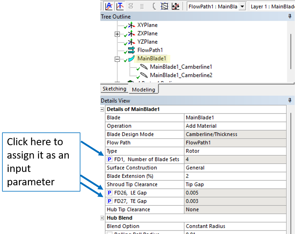
The blade count and LE and TE Gap parameters are set in “MainBlade” section of the three (Figure 1).
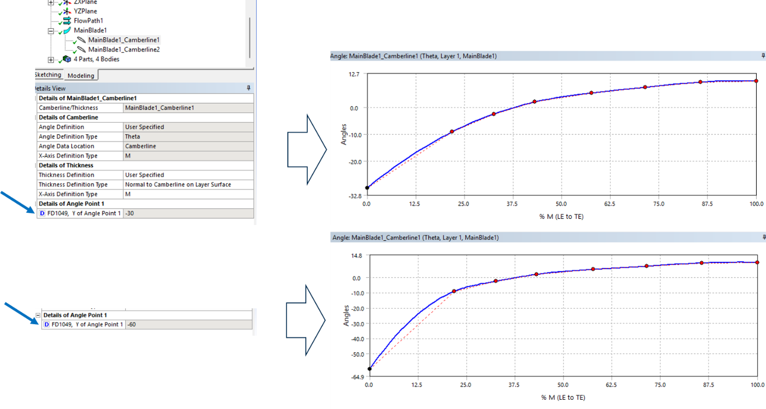
The Leading Edge (LE) Blade Angle and, more broadly, the entire blade profile can be modified by adjusting the control points that define the blade centerline. These points provide a convenient way to parameterize the blade shape while maintaining a smooth and manufacturable geometry.
For this study, the first centerline control point near the leading edge was selected as the design parameter to vary the inlet blade angle. Adjusting this point changes the local orientation of the blade at the inlet and influences how the incoming flow enters the blade passage. In addition to altering the LE angle, the modification introduces subtle changes to the overall blade profile.
Figure 2 compares two blade geometries generated using different inlet angle settings, illustrating how variations in the leading-edge control point affect both the LE blade angle and the resulting blade shape.
Defining Output Parameters
While the input parameters define the geometric variations to be investigated, output parameters are used to measure the performance of each design. Ansys Workbench allows virtually any solution quantity to be exposed as an output parameter, enabling engineers to evaluate how changes in geometry affect the blade’s performance.
For this study, Hydraulic Efficiency was selected as the primary output parameter. Unlike pressure head alone, hydraulic efficiency provides a more comprehensive measure of blade performance by accounting for both the energy transferred to the fluid and the mechanical power required to drive the rotor. As a result, it serves as an excellent metric for comparing different blade designs and identifying configurations that deliver the highest performance with the least energy input.
Hydraulic efficiency is calculated as:
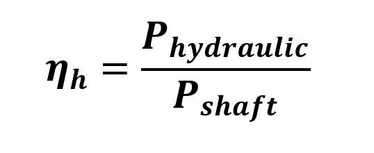
where the hydraulic power is determined from the pressure rise and volumetric flow rate,
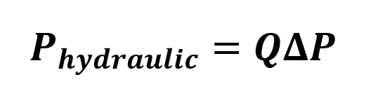
and the shaft power is calculated from the rotor torque and rotational speed,
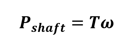
To facilitate the hydraulic efficiency calculation, all quantities required by the above equations—including pressure head, mass flow rate, torque, rotational speed—were also exposed as additional output parameters. While these parameters are not used directly in the design exploration study, they provide the necessary inputs for the efficiency calculation and offer valuable insight into the performance of each design point.
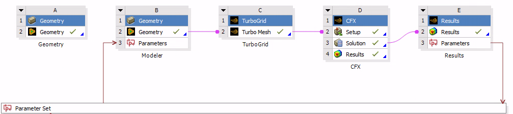
Once the input and output parameters have been defined, Ansys Workbench automatically adds a Parameter Set to the project schematic, as shown in Figure 3. This parameter set acts as the hub for all design exploration activities, providing a centralized interface for managing geometric design variables and monitoring simulation results as new design points are evaluated.
Double-clicking the Parameter Set opens the parameter table, where all input and output parameters are displayed. This interface provides a centralized location for managing design variables, reviewing performance metrics, and preparing the model for design exploration studies (Figure 4).
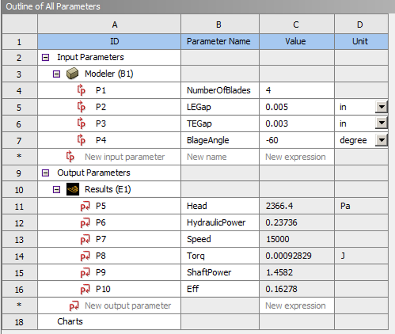
You will notice that the parameter table contains several additional output parameters beyond hydraulic efficiency, including Pressure Head, Hydraulic Power, Rotational Speed, Torque, and Shaft Power. Although these quantities are not required as standalone outputs for the current study, exposing them as parameters provides greater flexibility during the design exploration process.
These additional outputs can be used to define supplementary objectives or constraints during the optimization stage. For example, an optimization study could be configured to maximize hydraulic efficiency while simultaneously limiting torque requirements or achieving a target pressure head.
Furthermore, if hydraulic efficiency had not been explicitly defined as an output parameter in CFD-Post, the available output quantities could still be combined within the Design Exploration module to create a derived objective function. This approach allows performance metrics such as hydraulic efficiency to be calculated directly within the optimization environment, providing additional flexibility when defining optimization goals.
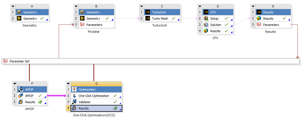
After defining the input and output parameters, the Sensitivity (AMOP) and Optimization systems are added to the Workbench project, as shown in Figure 5. These modules provide the framework for investigating parameter influences and identifying optimal blade designs based on the selected performance objectives.
The sensitivity analysis reveals the relative influence of each input parameter on the selected output responses. Using the generated response surface, Workbench quantifies how changes in blade count, LE gap, TE gap, and LE blade angle affect hydraulic efficiency and any other defined performance metrics.
Figure 6 shows the sensitivity chart for hydraulic efficiency. Among the four design variables considered in this study, the analysis clearly identifies which parameters have the greatest effect on performance and which have a relatively minor impact over the investigated design space.
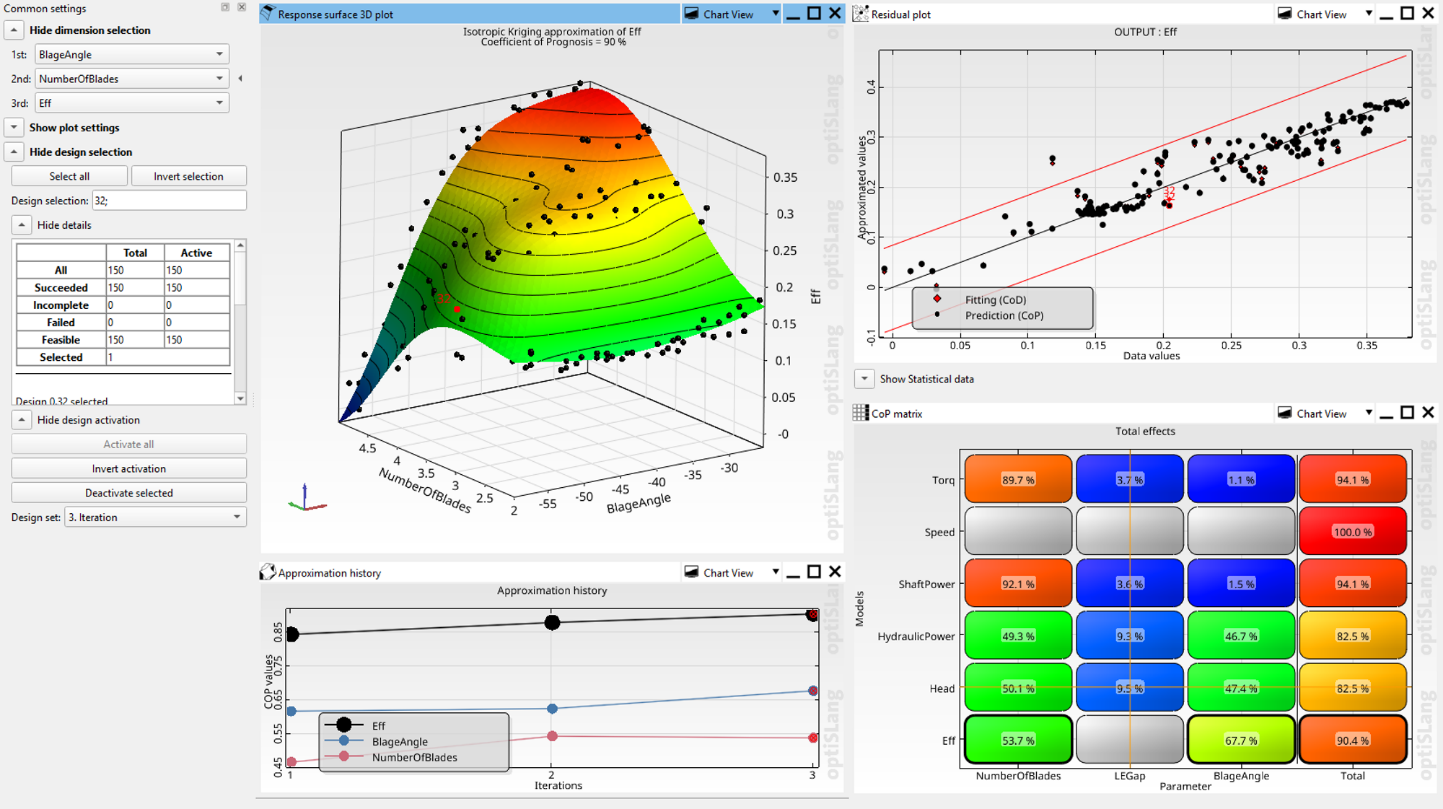
The quality of the response surface can be evaluated using the Coefficient of Prediction (CoP), which measures how accurately the response surface predicts results that were not used during its construction. For this study, a response surface was generated using Hydraulic Efficiency as the output parameter and Number of Blades and Leading Edge Blade Angle as the input parameters. The resulting response surface achieved a CoP value of 0.90, indicating excellent predictive capability within the investigated design space.
In general, a CoP value close to 1.0 indicates that the response surface accurately captures the relationship between the input and output parameters, while lower values suggest that additional design points or a different response surface formulation may be required. With a CoP of 0.90, the generated response surface provides a reliable representation of how variations in blade count and blade angle influence hydraulic efficiency, making it well suited for sensitivity analysis and optimization.
Although a CoP of 0.90 is considered very good for engineering design studies, there are several ways to further improve the predictive accuracy:
- Increase the number of design points used to build the response surface.
- Expand the design space to better capture nonlinear parameter interactions.
- Refine the sampling around regions with steep performance gradients.
- Introduce additional blade design variables, such as LE gap and TE gap, into the response surface.
- Perform additional CFD simulations to validate and refine the response surface in areas of higher uncertainty.
For the purposes of this study, however, the CoP value demonstrates that the response surface adequately represents the relationship between the selected blade design variables and hydraulic efficiency, providing confidence in the sensitivity and optimization results that follow.
With the response surface validated, the optimization study was used to identify the blade design that maximizes hydraulic efficiency. Rather than performing a full CFD simulation for every candidate, the optimizer leveraged the response surface to evaluate approximately 1,000 design variations within seconds.
Figure 7 summarizes the Ansys Workbench blade optimization results, showing the explored designs, the optimal candidate, and the corresponding input parameter values that define the blade geometry. The optimum design is identified based on the objective of maximizing hydraulic efficiency.
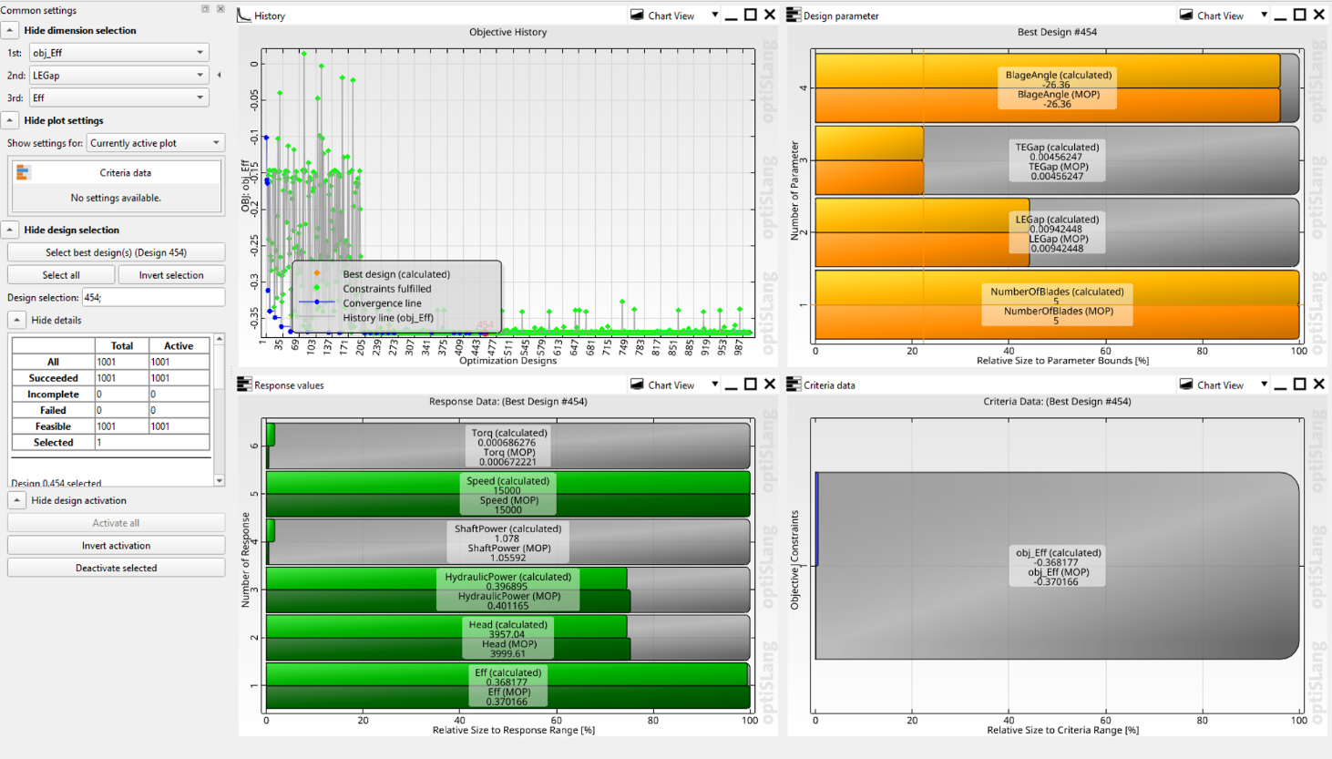
To confirm the prediction, a validation analysis was performed by updating the workflow with the optimal parameter values and running a full CFD simulation. The validated efficiency showed excellent agreement with the predicted value, demonstrating that the response surface accurately captured the relationship between the design variables and blade performance.
The close agreement between the predicted and simulated results provides confidence in the optimization process and demonstrates how Design Exploration can efficiently identify high-performance blade designs while minimizing the number of computationally expensive CFD simulations required.
Conclusion to Ansys Workbench Blade Optimization
A well-structured workflow is essential for modern blade design because it enables engineers to move beyond evaluating a single design and toward systematically improving it. By integrating geometry creation, meshing, CFD simulation, parameter management, sensitivity analysis, and optimization within a single Ansys Workbench environment, the entire design process becomes automated, repeatable, and scalable. This unified workflow eliminates much of the manual effort traditionally required to investigate design alternatives and provides a framework that can be readily adapted to different turbomachinery applications.
This article demonstrated how a baseline blade model can be transformed into a parametric design exploration workflow by defining key geometric inputs, selecting meaningful performance metrics, and leveraging Workbench’s sensitivity and optimization capabilities. Once established, the workflow automatically propagates design changes through geometry generation, mesh creation, simulation, and post-processing, allowing engineers to efficiently evaluate a large number of design variations.
The ability to generate response surfaces, identify influential design variables, and rapidly explore thousands of potential designs provides valuable insight into blade performance while significantly reducing computational costs. Most importantly, the final validation analysis confirms that the optimized design remains consistent with the underlying CFD model, ensuring confidence in the results.
Although the example presented here focused on blade count, leading-edge gap, trailing-edge gap, leading-edge blade angle, and hydraulic efficiency, the same methodology can easily be extended to additional geometric parameters, performance objectives, and optimization strategies. As a result, this workflow serves as a practical foundation for developing high-performance blade designs and accelerating the overall turbomachinery development process.
Additional Resources
The following video provides a step-by-step walkthrough of the parametric blade design workflow described in this article, including geometry parameterization in BladeModeler, CFD setup in CFX, sensitivity analysis, response surface generation, design optimization in Ansys Workbench, and validation of the optimized blade design using a full CFD simulation.
Optimize Turbomachinery Designs with Simulation
See how SimuTech can help you combine Ansys Workbench, CFX, BladeModeler, and design exploration tools to evaluate design variables, identify performance drivers, and accelerate CFD-driven blade optimization.

Ertan Taskin, Ph.D., Chemical Engineering
Principal Engineer, SimuTech Group
Ertan is a Principal Engineer with more than two decades of experience in CFD, fluid-structure interaction, and biomedical device design. He has advanced ventricular assist devices, transcatheter heart valves, and artificial lungs through hydraulic optimization, in vitro validation, predictive modeling, and AI-driven data analysis. His recent work integrates machine learning for performance prediction and design optimization. His career includes senior engineering roles at Medtronic, HeartWare, Roketsan, and Ozen Engineering, where he led projects spanning medical devices and aerospace propulsion. Ertan’s expertise includes blood damage modeling, uncertainty quantification, integrated thermo-fluid systems, and AI-assisted simulation workflows. He holds a Ph.D. in Chemical Engineering from Worcester Polytechnic Institute, along with Master’s and Bachelor’s degrees in Chemical Engineering from Middle East Technical University.