
 Contact Us
Introduction
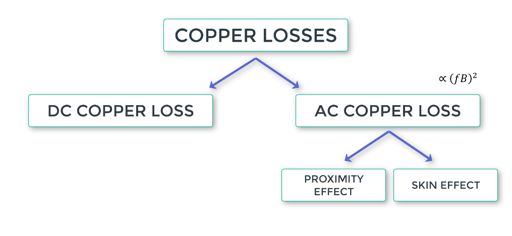
Skin and proximity effect losses can significantly influence the efficiency and thermal performance of electric motors, particularly in high-speed applications. These electromagnetic phenomena alter current distribution within stator winding conductors, increasing AC resistance and contributing to additional power losses.
Ansys Motor-CAD helps engineers evaluate these losses through finite element analysis (FEA), accounting for conductor geometry and placement within stator slots. This article examines the causes and compares the Full FEA and Hybrid FEA methods available for analyzing stator winding performance.
Video: Analyzing Skin and Proximity Effect Losses in Ansys Motor-CAD
The following video demonstrates how Ansys Motor-CAD evaluates skin and proximity effect losses in electric motor stator windings. It explores Full FEA and Hybrid FEA methods for calculating AC conductor losses, highlighting how conductor placement and simulation settings influence loss predictions and computational efficiency.
Understanding Skin and Proximity Effect Losses
- Skin effect: AC fields induce current loops in the conductors increasing the flux linkage in the center, leading to higher reactance in this location, the result is the current flows near the surface instead of in the full cross section area, leading to higher resistance and higher losses.
- Proximity effect: similar to skin effect, but in this case the redistribution of the current is due to the flux produced by nearby conductors. Main source of AC conductor losses.
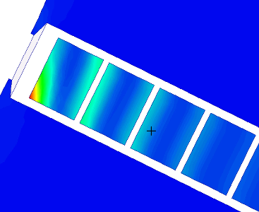
The conductors positioning has a huge impact:
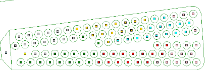
In high speed electric motor applications, skin and proximity effect losses are significant factors that can affect performance and efficiency.
Full FEA Models: High Accuracy, Longer Calculation Times
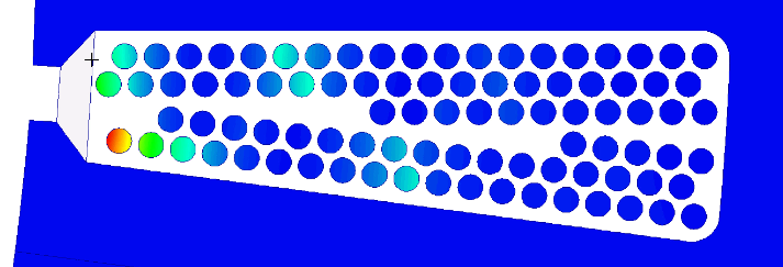
Ansys Motor-CAD uses full finite element analysis (FEA) to accurately calculate skin and proximity effect losses in stator windings, accounting for conductor placement within the slot. Both single-slot and multi-slot calculations are supported. While full FEA provides highly accurate results, analyzing slots with numerous conductors can take several hours. Motor-CAD also allows engineers to adjust conductor positions and optimize their arrangement within the slot.
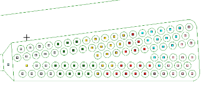
MotorCAD plots Ohmic loss distribution as well:
Hybrid FEA Models: Balance Between Accuracy and Speed
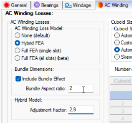
To address the trade-off between accuracy and computational efficiency, MotorCAD can utilize Hybrid FEA models, which offer high accuracy while solving very quickly. However, particularly when calculating stranded winding AC losses, the hybrid model may need to be fine-tuned by comparing its results with the full FEA solution.

Evaluating Stator Winding Losses with Ansys Motor-CAD
Understanding skin and proximity effect losses is an important part of improving electric motor efficiency and thermal performance. By evaluating conductor placement and AC loss distribution, engineers can identify opportunities to refine stator winding designs.
Ansys Motor-CAD provides Full FEA and Hybrid FEA approaches for analyzing these effects, allowing engineers to balance simulation detail with computational efficiency based on their design requirements.