Ansys Mechanical (Workbench) has a Construction Geometry object for Surfaces, as well as for Paths that cut through a solid geometric entity. A Surface object is positioned by a user-created coordinate system, and can be used to measure the net force in the model across a cut represented by the surface cutting through scoped geometry. This document briefly reviews using a surface to measure force at such a cut. Note: Requires Ansys 14.5 or later
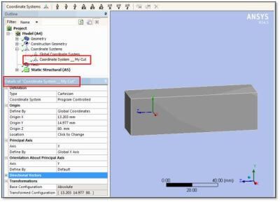
To position a Section in Construction Geometry requires that the user create a coordinate system. Various means can be employed to position the origin of a coordinate system, and to orient its X, Y and Z axes. In the figure below, a Cartesian coordinate system has been positioned with its X-Y plane across a solid body of interest. If moments are to be measured where the X-Y plane cuts across a body, the origin of the coordinate system should be positioned at the centroid of the shape formed where the plane cuts the body.
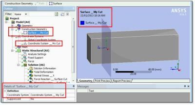
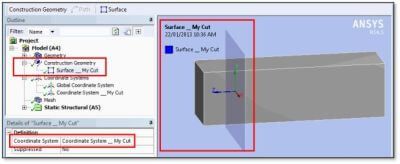
In the figure below, we see a Construction Geometry Surface positioned on the figure above coordinate system.
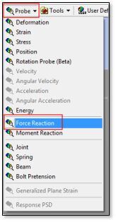
Once the Surface of interest has been created in the Construction Geometry branch, the model can be solved, and a Force Reaction probe can be inserted in the Solution branch for the environment of interest.
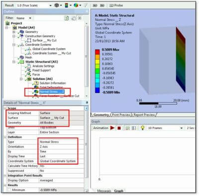
Various results can be scoped to the location where a Construction Geometry Surface cuts through scoped bodies in a model. The following figure illustrates mapping of Normal Stress in the Z direction from a body to a surface:
In addition to mapping of results directly onto surfaces, Probes can be used to examine forces across these surfaces.
In the figure below, a Force Reaction is located at a Surface, which is defined to be the Construction Geometry Surface defined earlier. The result is scoped to the solid body geometry, and the Results listed show forces in X, Y and Z in the Orientation indicated by the selected coordinate system.
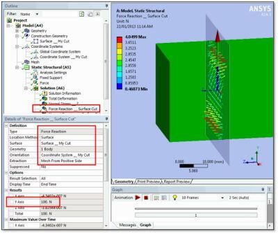
Note that “Extraction” is set to “Mesh From Positive Side”. If the negative side is selected, the forces will be equal but opposite those listed.
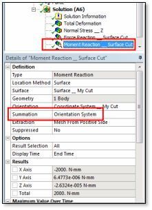
Requesting a Moment Reaction, as illustrated in the figure below, is more difficult because a Summation point needs to be selected. If “Orientation System” is chosen, then the “Orientation” coordinate system must have its origin in a suitable location—usually the centroid of the shape of the cut that the surface makes where it cuts through the solid geometry. If the Summation point is not suitable located, the moment reaction result will be invalid.
As in the case of a Force Reaction, note that setting of the “Extraction” side will affect the sign of the results.
A Construction Geometry branch in the Workbench Mechanical outline can be used to position a Surface that cuts through a solid model. Such a surface is positioned by a user-defined coordinate system in the Coordinate Systems branch.
Once such a surface exists, a Force Probe can use it to measure force carried across a cut through a selection of solid bodies. The cutting surface should be properly located in space, and the body or bodies of interest are scoped so that the force measured is only for the bodies of interest. A coordinate system can be chosen to orient the meaning of the X, Y and Z directions in the force listing.
Moments can also be considered, but a summation point must be properly indicated.
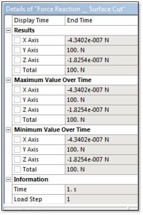
The measured results can be parameterized, and used in searches with the Parameter Manager, or in Design Explorer. Forces in X, Y and Z are listed in the Details output, as shown in the figure below.
The latest Ansys Software releases to support with force on a construction geometry surface
Ansys Mechanical Workbench is a top-tier finite element solver with capabilities to enhance your modeling in the areas of structural, thermal, acoustical, transient, and nonlinear behavior.
Ansys LS-DYNA simulates the response of materials to short duration severe loading. Today, it is the single most used explicit dynamics simulation program worldwide. Best suited for highly technical users.
Ansys EnSight is the market leader for data visualization. Its post-processing tool includes models with more than hundreds of millions of cells, providing engineers with insights unavailable elsewhere.
Ansys Motor-CAD is a specialized electric machine design tool that allows for quick multiphysics simulation over the entire torque-speed working range.
Ansys HFSS simulates 3-Dimensional full-wave electromagnetic fields for accurate and rapid design of high-frequency and high-speed electronic components.
Gain quick, accurate electronic hardware life predictions with Ansys Sherlock, the only PoF (Reliability Physics/Physics of Failure) software that provides insight at each the system, board, and component levels.
A comprehensive solution for designers, engineers, and analysts that spans the full workflow, from design for additive manufacturing (DfAM) to validation, process simulation, and material exploration
Component-level and system-level simulations are provided by the extensive range of photonics simulation to improve performance, lower the price of physical prototyping, and shorten time-to-market.
Ansys Icepak provides specialized electronic cooling solutions that utilize the industry leading CFD solver for T&F flow analyses of integrated circuits, PCBs and electronics.