Performing Harmonic Response Analysis | Ansys Workbench
Ansys Workbench Mechanical can perform harmonic response analysis, by either modal superposition, or by full harmonic analysis. Measurement of face rotation is sometimes of interest to customers. If a remote point is associated with a face of interest, rotation of that remote point can be measured in an APDL Commands Object, and reported to the user, with the option of creating an output parameter from the rotation value.
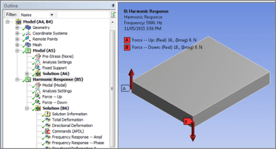
In the figure above, the far end of a plate has been fixed. The nearer end has harmonic loads applied at two edges, one pointing up, and one pointing down. The objective is to excite the plate at frequencies around a mode of vibration that has the twisting motion implied by these forces.
End face rotation will be measured, using a Remote Point that is associated with the face, and set to “Deformable” so that the behavior of the model is not influenced. Associating a remote point with a face meshed with a large number of nodes can increase solution time and memory requirement—setting a pinball radius can reduce this.
Recent features in Ansys that make it easier to find amplitude results in harmonic analysis are illustrated here. Settings that measure face rotation in harmonic analysis will be reviewed.
Details of Rotation Measurement in a Harmonic Response Analysis
In the Workbench project page, a modal analysis can be linked to a subsequent harmonic response analysis:
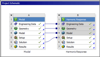
The modal analysis can be helpful before a harmonic run in order to discover at what frequencies a structure may respond substantially to an excitation. If a modal analysis has included enough frequencies to more than cover the range of excitation frequencies in a harmonic response analysis, then modal superposition can be used in the harmonic response analysis, as an alternative to full harmonic response analysis.
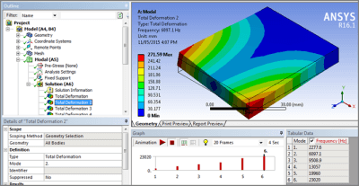
In the figure below, it can be seen that the second mode involves rotation of the free end of the cantilever plate around the Z axis, at a frequency of 6097.1 Hz. Note: the predicted frequency can be sensitive to the mesh density.
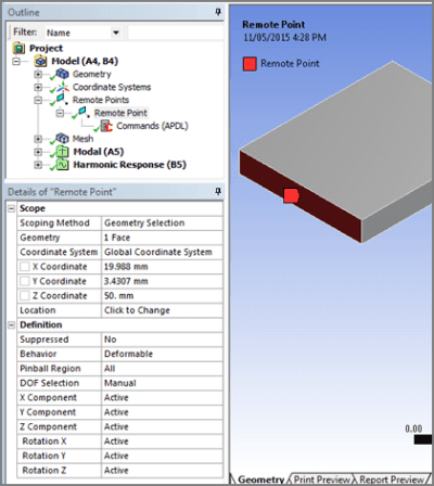
In the figure below a Remote Point has been created and automatically positioned at the centroid of the end face on the plate. All degrees of freedom are active, and the associated face is set to the default “Deformable” so that it can flex as if the Remote Point was not there.
An APDL Commands Object can be inserted for the Remote Point, and used to remember the number of the node assigned to the remote point. The variable “Measure_Pilot” is created for this purpose, as seen below.
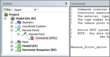
Here is the APDL command:
Measure_Pilot=_npilot
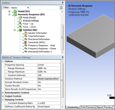
In the figure below, a Harmonic Response has Analysis Settings input to indicate a range of frequencies of interest, and the number of intervals between frequencies to be analyzed:
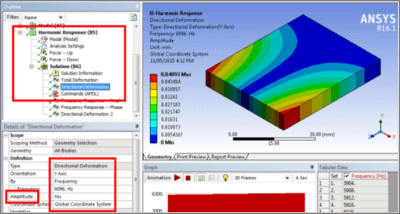
With loading as described in the first figure, the amplitude of Y displacement calculated at 6096 Hz can be displayed as in the figure below, at a frequency close to resonance:
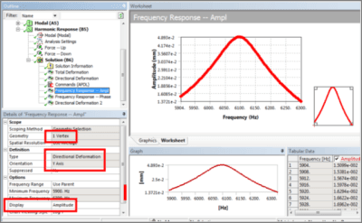
Insight as to the peak response around a resonant frequency can be obtained in a Frequency Response plot set to show Amplitude, as below for a vertex at a corner of the free face of the plate:
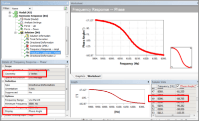
Further insight results from a phase plot for the vertex, as in the figure below. Note the phase angle near resonance:
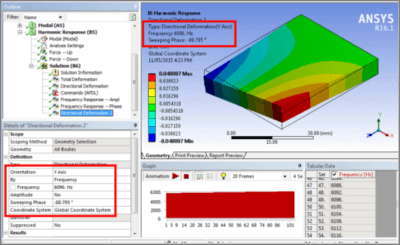
The frequency and phase angle as seen above in the above figures can be used to obtain a directional deformation plot in which the values are not absolute values. Since the phase angle is entered for the frequency, we see in the figure below the magnitude of the displacement without the absolute value being assigned:
An APDL Commands Object can be used to load a result of interest, and read the amplitude of vibration at a remote point. This is illustrated in the figure below, using the node number recorded in the figure above:
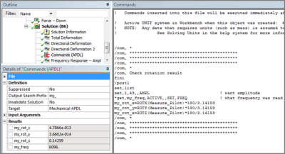
Here are the APDL commands used in the figure above to measure and report the rotations about the X, Y and Z axes. In this example, the user provides the substep number that corresponds to the frequency of interest. Users must remember to request Amplitude in the SET command:
/com, *
/com, *******************************************
/com, *******************************************
/com, *******************************************
/com, *
/com, Check rotation result
fini
/post1
set,list
set,1,49,,AMPL ! want amplitude
*get,my_freq,ACTIVE,,SET,FREQ ! what frequency was read
my_rot_x=ROTX(Measure_Pilot)*180/3.14159
my_rot_y=ROTY(Measure_Pilot)*180/3.14159
my_rot_z=ROTZ(Measure_Pilot)*180/3.14159
/com, *
/com, *******************************************
/com, *******************************************
/com, *******************************************
/com, *
Note that the SET command above could directly request a frequency with the Time argument:
SET, Lstep, Sbstep, Fact, KIMG, TIME, ANGLE, NSET, ORDER
Result check: Divide vertical movement (left – right vertex) by width and rotation is estimated:
ATAN(2*0.04893/39.975) = 0.14026 degrees
This angle is close to that of the remote point in Figure 11, which considers all of the nodes on the face.
Conclusions | Harmonic Response Analysis
Workbench Mechanical can be used to perform a Harmonic Response dynamic analysis. A remote point can be created, and used in APDL commands to measure a rotation angle amplitude at a frequency of interest.
A modal analysis is often performed prior to another dynamic analysis in order to characterize the system of interest. Because a harmonic response analysis is linear, modal superposition can be used if desired, as long as enough modes are extracted to more than cover the range of harmonic excitation frequencies.
Plots of frequency response and phase response can augment an understanding of a harmonic response analysis. For user convenience, recent Ansys versions permit direct measurement of amplitude of a harmonic response, without going through combinations of real and imaginary components, or of phase and amplitude.
This article illustrates APDL commands that can return rotation angle at a chosen frequency.
- For guidance on Ansys Post-Processing
- For Support on performing ‘EKILL‘ in Workbench
- APDL Command Objects post-Spectral Analysis
- For Separating DB Database Files from RST Files
- Measuring Geometric Rotation in Mechanical WB
- CAD Geometry Deformation Plasticity