Composition and Construction Characteristics of Strain Gages
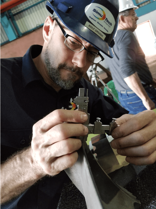
When setting up and reviewing strain gage patterns and orientation, it is important to review several components, such as rosette stacking, prior to field implementation. In a multiple-grid gage, the gage pattern refers to the shape of the grid, the number and orientation of the grids, the solder tab configuration, and other construction aspects that are conventional for that pattern.
The “Gage Pattern” columns of our strain gage data book show all the details of the grid and solder tab setups.
The list’s wide selection of patterns is intended to meet the complete spectrum of normal gage installation and strain measuring needs.
Pattern compatibility for a certain application with single-grid gages is primarily determined by the following factors:
- Strain Gage Solder Tabs
- Strain Gage Grid Width
- Strain Gage Resistance
- Plurality (or Singularity) of Stress Test
- Rosette Stacking & Positioning
- Surface Type and Environment
Width, Resistance, Stacking, Surfaces, and Environment | Strain Gage Orientation
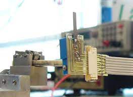
Solder Tabs & Terminals | Strain Gages
When setting up and reviewing strain gage patterns and orientation, the solder terminals should be fitted between the connecting cables and the strain gauge itself. That is, for strain gauges containing leads or wires.
As it relates to positioning, Solder tabs should also be consistent in size and orientation with the available area for a given installation site.
It’s also critical that the tab arrangement doesn’t place an undue burden on the installer’s ability to make suitable leadwire connections.
Strain Gauge Grid Width | Wider Grids vs. Narrow Grids
When the test specimen surface has significant strain gradients perpendicular to the gage axis, a small grid will reduce the averaging error.
When accessible and appropriate for the installation site, wider grids will increase heat dissipation and gage stability.
This is especially observable, as noted by our engineers, when the gage is to be put on a material or specimen with poor heat transfer qualities.
Strain Gauge Resistance | High-Resistance vs. Low Resistance
Gage resistance — In some cases, the grid resistance — typically 120 ohms vs. 350 ohms — is the only variation between two gage designs available in the same series.
When the option is available, the higher-resistance gage is preferred since it reduces the rate of heat generation by a factor of three (for the same applied voltage across the gage).
Increased gage resistance also reduces leadwire effects such circuit desensitization induced by leadwire resistance and undesired signal variations produced by leadwire resistance changes with temperature fluctuations.
When the gage circuit incorporates switches, slip rings, or other sources of random resistance variation, higher resistance gages working at the same power level increase the signal-to-noise ratio.
Single-Grid Strain Gages
A single-grid gage would generally be employed in experimental stress analysis only when the stress condition at the measurement location is known to be uniaxial and the directions of the primary axes are known with good accuracy (5°).
These criteria significantly limit the usefulness of single-grid strain gages in stress analysis. Moreover, failure to account for the biaxiality of the stress state can result in considerable inaccuracies in the level of stress inferred from single-grid gage measurements.
Biaxial Stress States & Strain Gage Alignment
A two- or three-element rosette is necessary to determine the major stresses in a biaxial stress state, which is a common instance requiring strain measurement.
When the principal axes’ directions are known ahead of time, a two-element 90-degree (or “tee”) rosette with the gage axis aligned to correspond with the principal axes can be used. One of several considerations can occasionally be used to establish the directions of the major axes with acceptable accuracy.
For example, in a cylindrical pressure vessel, the shape of the test item and the mechanism of loading may be such that the directions of the primary axes are clear from the symmetry of the situation. Computing photo stress testing can also be used to define the primary axis.
General Surface Applications of Strain Gages
When the directions of the primary axes are not known from other considerations, a three-element rosette must be employed to determine the principal stress magnitudes in the most general situation of surface stresses.
When setting up and reviewing strain gage patterns and orientation, note that the rosette can be put in any orientation. However, it is most commonly fixed so that one of the grids is aligned with a major axis of the test object. Rosettes with three elements come in 45-degree rectangle and 60-degree delta forms.
The rectangular rosette is the most common choice because the data reduction work is easier in this configuration.
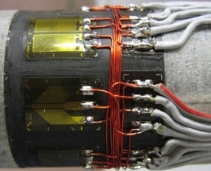
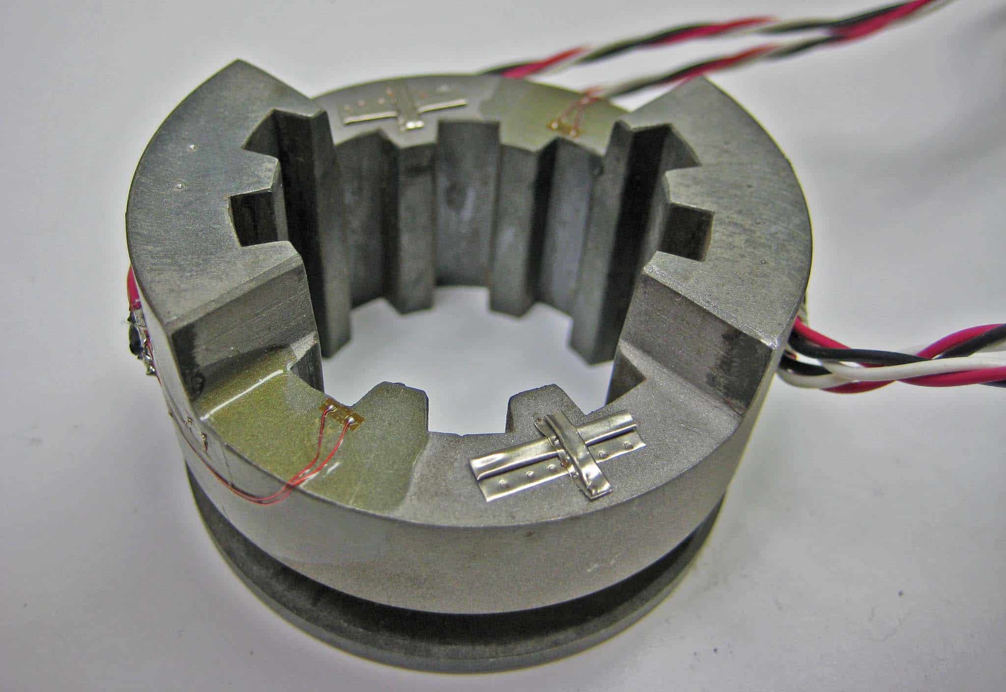
Considerations for Single-Plane and Stacked Rosettes
When using a rosette, the differences in properties between single-plane and stacked rosettes should always be considered.
In terms of heat transfer to the test specimen, the single-plane rosette outperforms the stacked rosette for any given gage length, offering improved stability and accuracy for static strain measurements.
Furthermore, because all grids are as close to the test surface as feasible, the single-plane rosette will yield more accurate strain data when there is a considerable strain gradient perpendicular to the test surface (as in bending). Another thing to keep in mind is that stacked rosettes are less adaptable to curved surfaces than single-plane rosettes.
Determination of High Strain Gradients with the Test Surface
Strain gradients are considered critical and sensitive indicators of structural health.
Yet, the power of singularity for materials with strain gradient effects is often different from that for conventional materials.
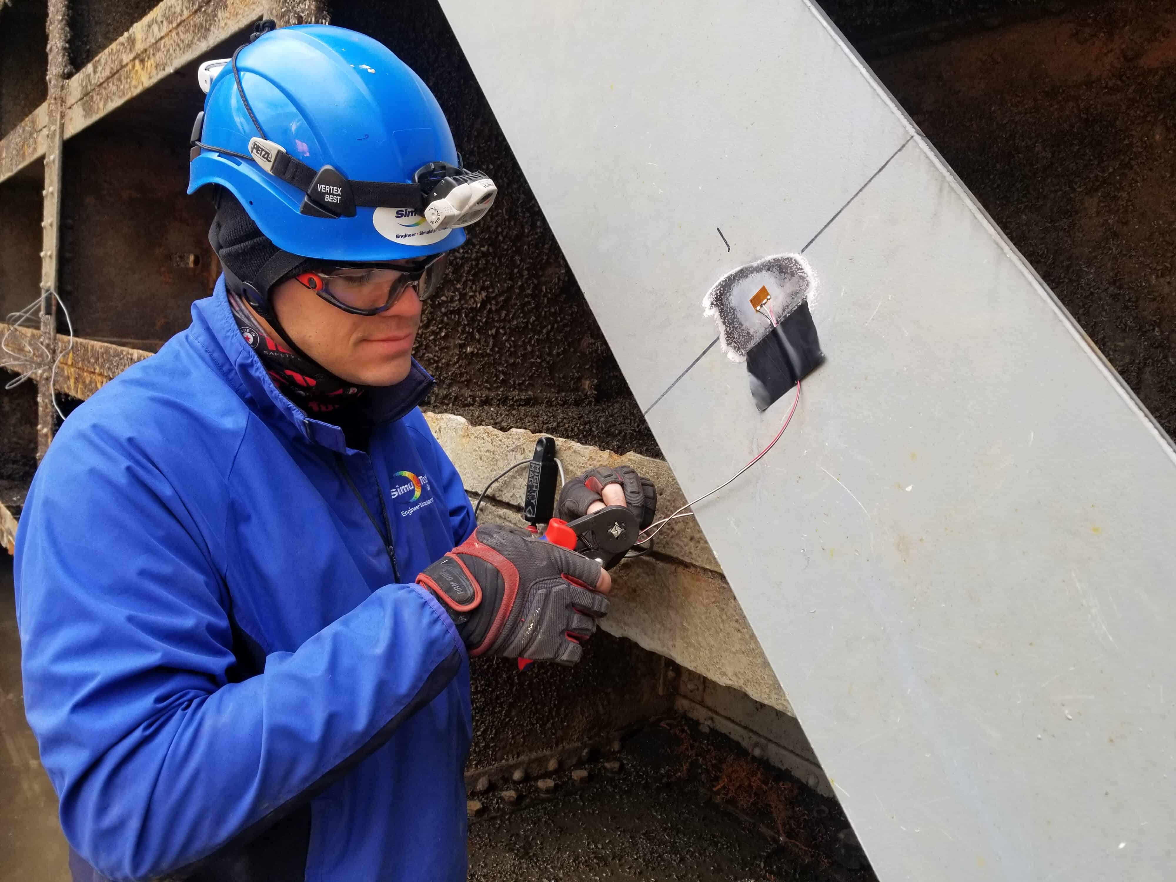
As it relates to in-the-field strain gauge testing, it is imperative to determine when there are high strain gradients in the plane of the test surface, as is frequently the case.
The single-plane rosette, on the other hand, can generate strain indication inaccuracies since the grids sample the strain at various positions. The stacked rosette is usually preferred for these applications. When room for installing the rosette is restricted, the stacked rosette is also beneficial in this regard.
Related Strain Gage Engineering Articles
How to Choose the Correct Strain Gage for Testing
Strain Gauge selection may appear to be a simple task with little significance for the stress analysis, but this is far from the case. Learn why.
What are the different types of Strain-Sensitive Alloys?
The strain-sensitive alloy employed in the foil grid is critical in determining a strain gage’s working properties. Learn the benefits and utility of each alloy type.
What Backing Materials are Used in Strain Gages?
Strain gages come with two types of backing materials, along with corresponding alloy combinations, unique manufacturing features, and created as micro-systems.
Determine the Optimal Gage System, or Series
So, you’ve determine a need for strain gage testing. Now, a choice must be made via available gage systems, each of which includes unique design features and construction aspects.
Recommended Gages for Specific Test Profiles
Considerations for the Strain Gage Series selected must include that of specific test profiles, such as strain type, operating temperature, measurements duration, and more.
Best Practices when Selecting Gage Length
When possible, the gage length should be no more than 0.1 times the radius of a hole, fillet, notch, or corresponding dimension of any other stress raiser. Learn why.
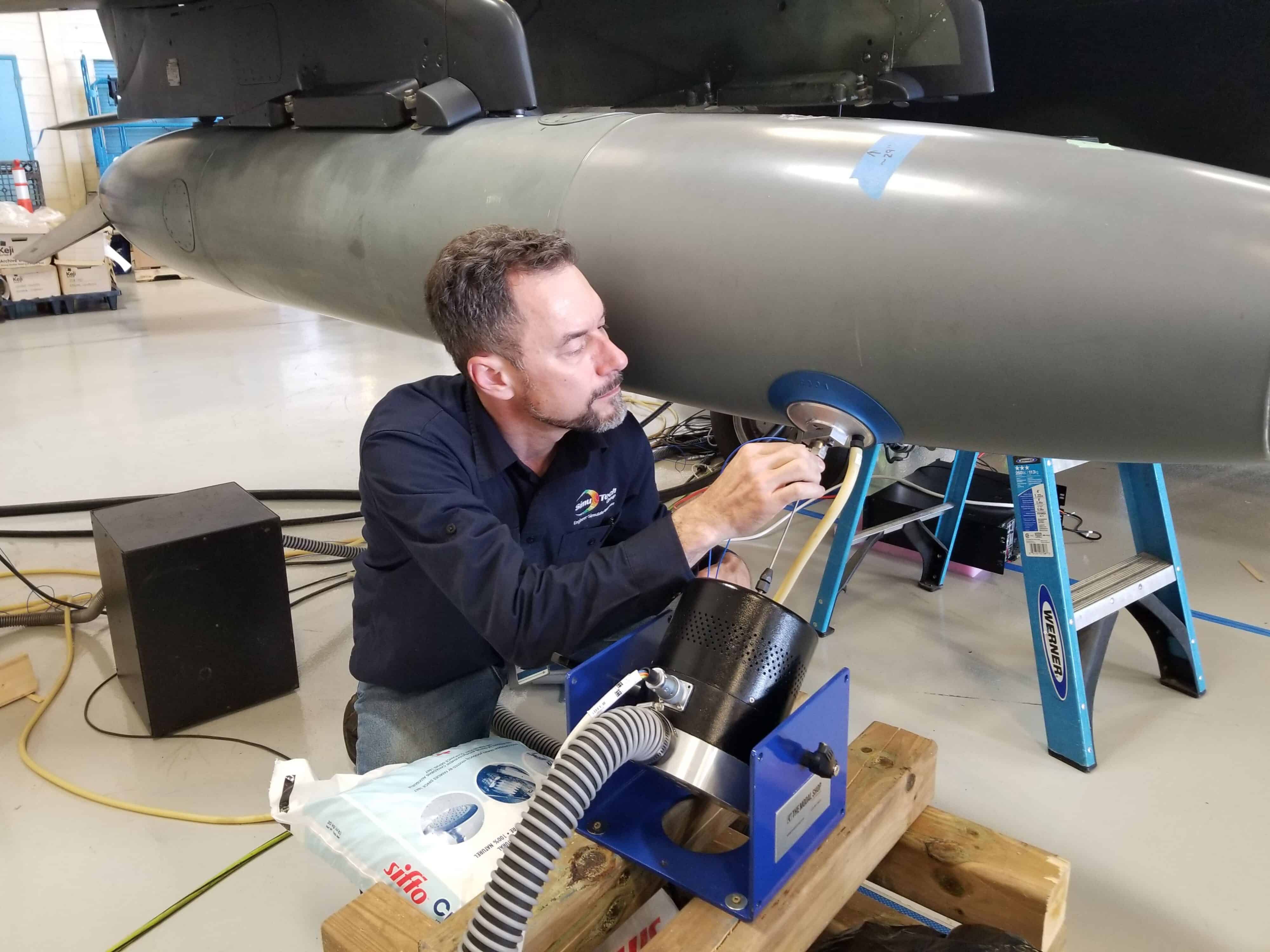
Application of Strain Gage Pattern Analysis & Testing
Strain gages are ideal for verifying stress and displacement simulation models. The strain measurements are taken at specific locations and correlated with the optimal strain gage pattern orientation, and general testing protocols determined via reiterative simulation results.
Modeling assumptions such as boundary conditions, contacts, and loads may be updated to make the simulation better fit the observed behavior.
Once the model accurately reflects the measurements, more detailed information about the system can be inferred.
In addition, simulations of the modified system can be used to predict behavior with confidence.
SimuTech Group specializes in both strain gage measurement as well as simulation, allowing seamless support when conducting investigations.
Contact for Strain Gage Testing Services
Additional Mechanical Testing Services Offered
Turbine Blade Frequency
For new, refurbished, or reverse engineered turbine blades (buckets) to ensure that natural frequencies are within specifications.
Torsional Vibration
Determine the natural frequencies and mode shapes of a rotor train as it twists about the axis of rotation.
Vibration Diagnostics
Identify the root cause of noise and vibration problems in machinery via ODS, spectral, order tracking or joint time frequency analysis.