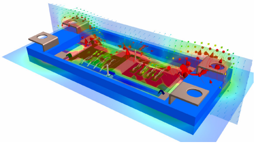
Ansys HFSS Propagation Constants & Optimization | Ansys Webinar:
This webinar discusses the latest best practices in antenna design and optimization using HFSS, along with best-practices on writing propagation constant formulas and creating dispersion diagrams.

Basics of a Dispersion Diagram
In order to obtain a dispersion diagram for the first mode of a parallel plate waveguide, we want to apply HFSS. A dispersion diagram shows the propagation constant as a function of frequency and essentially indicates the amount of phase shift present in a material at a given frequency.
A parallel plate waveguide’s propagation constant, = xkx + yky, can be represented as a vector quantity because it permits two-dimensional wave propagation. A unit-cell must be specified, and the proper periodic boundary conditions (PBCs) must be used, in order to construct the dispersion diagram. A symmetric unit-cell is described in this manner for the sake of simplicity and the fact that a parallel plate waveguide can be thought of as a periodic structure.
Ansys HFSS Propagation Constant & The Brillouin Zone
Additionally, the high-symmetry locations for the Brillouin zone are defined as
(Kxp = 0; kyp = 0) = Г
(kxp =, kyp = 0) = X
(kxp = kyp = π) = М
The Brillouin zone is the most fundamental area for identifying a unit-propagation cell’s vector; in essence, if all of the propagation vectors in the Brillouin zone are defined, the entire periodic structure’s characteristics are obtained. As shown by the path shown on the Brillouin zone, the dispersion diagram will start at, go to, then to M, and finally return to.
Parallel Plate Waveguides & HFSS Propagation Constant
One of the waveguides that is most frequently covered in electromagnetics textbooks is the parallel plate waveguide. Two metallic plates, either separated by air or a dielectric substrate, make up a parallel plate waveguide.
Although it is falsely believed that the plates can extend infinitely, microwave absorber/matched terminations are utilized at the waveguide’s outer perimeter. An essential TEM mode is supported due to the parallel plate waveguide’s dual metal construction. The eigenmode solver of HFSS is used in this tutorial to produce the dispersion diagram of a parallel plate waveguide with a dielectric substrate permittivity of 10.2 and a height of 2.54 mm. The subsequent engineering concepts are all are covered:
- Basics of a Dispersion Diagram
- HFSS Model Setup
- Boundary conditions that are repeated
- Setup for Analysis/Optometrics
- Plotting outcomes
Additional Ansys Software Tips & Tricks Resources
-
- Analyzing normal and Tangential Elastic Foundations in Mechanical
- Why Meshing is Crucial for FEA Fluid Simulations Prior to Prototyping
- For support on Contained Fluid FEA Modeling with HSFLD242 Elements
- For Exporting a Deformed Geometry Shape Post-Analysis in Mechanical
- Moreover, for guidance Multi-Step Analyses in Mechanical
- For Retrieving Beam Reaction Force in a Random Vibration Analysis
- Deploying Ansys Macro Programming vis *USE Command in Mechanical
- For replicating Fatigue Models from Start to Finish in Mechanical
- In addition, setting up Acoustic Simulations of a Silencer
- For a step-by-step guide on 2D to 3D Submodeling in Mechanical
- For modeling Pipe16 Circumferential Stress in Mechanical
- For Support on performing ‘EKILL‘ in Workbench
- APDL Command Objects post-Spectral Analysis
- For Separating DB Database Files from RST Files
- Measuring Geometric Rotation in Mechanical WB
- Explicitly, CAD Geometry Deformation Plasticity
- Offsetting a Temperature Result to Degrees Absolute
- For general guidance on Ansys Post-Processing
- Finally, for basic Ansys Software Installation and License Manager Updates


