Ansys HFSS

Design high-frequency electronics that work the first time. Ansys HFSS is the industry-standard 3D electromagnetic field solver for RF, microwave, and high-speed digital applications, helping you quickly validate antennas, packages, connectors, and PCBs before you ever build a prototype.

Perfect for: phased-array and radar systems · 5G/6G & wireless devices · high-speed interconnects & SerDes links · RF filters and matching networks · advanced applications such as quantum hardware and cryogenic RF packaging

3D Electromagnetic Field Simulator for RF and Wireless Design

Ansys HFSS gives you true-to-physics results for complex RF and high-speed structures, from single components to full systems. Whether you’re integrating multiple antennas on a crowded platform, routing dense high-speed channels across a PCB, or packaging RF front-end modules, HFSS lets you explore more design options with confidence.

Engineers use HFSS to:

  • Validate antenna patterns, gain, and efficiency in realistic mounting environments
  • Characterize S-parameters, crosstalk, and insertion/return loss for high-speed channels
  • Optimize RF components such as filters, couplers, baluns, and power dividers
  • Reduce EMC/EMI risk early, before hardware builds and compliance testing
  • Streamline component-to-system EM workflows from individual parts to full assemblies
  • Securely share encrypted 3D designs across teams and partners
  • Solve coupled EM systems that include multiple interacting components and physics
  • Automatically refine meshes with adaptive meshing to achieve reliable convergence
Far-field antenna pattern of International Space Station antenna using HFSS physical optics solver

Pioneering Antenna Design & Integration

Modern platforms are packed with antennas—cellular, GNSS, Wi-Fi, radar, satellite links, and more—all competing for space and spectrum. HFSS helps you understand how each antenna behaves once it’s installed on a real platform, so you can protect link budgets, reduce interference, and meet performance targets in the field.

In the modern era, there are antennas almost everywhere. Integrated ground-based communication systems now span to a variety of applications. From commercial uses like smartphones, RFID tags, and wireless printers to defense applications such phased array antennas for aircraft radar systems or autonomous vehicles.

Accuracy-and-Reliability-of-HFSS
HFSS-Simulation-Ansys-Software

Simulation, the Key to Robust Antenna Design & Performance

With HFSS, you can run fast “what-if” studies on antenna geometry, placement, and surrounding structures, so you can see how design decisions impact performance before committing to hardware.

  • Intricate Component Analyses
  • EMI/Co-Site Interference
  • Lightning Strike Simulation
  • Multi-Functional Antenna Design
  • Optimal Antenna Placement and Co-site
  • Variable Multi-Band Antenna System

Ansys HFSS Key Features

Engineers may use Ansys Electronics Desktop to diagnose, isolate, and remove EMI and radio-frequency issues (RFI) early in the design cycle by combining the unparalleled precision of Ansys electromagnetic 3D and 2.5D field solvers with the efficient circuit- and system-level solution in Ansys RF Option.

Users can use Electronics Desktop’s seamless workflow, which includes advanced electromagnetic field solvers, to predict EMI/EMC output of electrical devices by dynamically linking them to power circuit simulators. These integrated workflows eliminate expensive repeated EMC qualification checks and redundant design iterations.

Solving Electromagnetic Design Problems

Engineers may determine the overall performance of their electrical devices and build interference-free designs using several EM solvers designed to resolve a variety of electromagnetic problems, as well as the circuit simulators in Electronics Desktop.

Radiated and conducted emissions, susceptibility, crosstalk, RF desense, RF coexistence, cosite, electrostatic discharge, electric fast transients (EFT), blast, lightning strike effects, high intensity fields (HIRF), and radiation hazards are only a few of the issues that need to be addressed (RADHAZ), electromagnetic environmental effects (EEE), electromagnetic pulse (EMP) to shielding effectiveness and other EMC applications.

For modeling mounted antenna-to-antenna coupling, EMIT works hand-in-hand with Ansys HFSS to combine RF device interference analysis with best-in-class electromagnetic simulation. As a result, a complete solution for reliably predicting RFI effects in multi-antenna environments with multiple transmitters and receivers has been developed.

Mitigating RFI Challenges and Expenses

All significant RF interactions, including non-linear device component effects, are computed by EMIT’s powerful analysis engine. In a laboratory environment, diagnosing RFI in complex environments is notoriously challenging and costly.  Fortunately, using EMIT’s dynamic related results views, the root-cause of any interference can be quickly identified by graphical signal trace-back and diagnostic summaries.  The diagnostic markup displays the precise origin and direction that interfering signals take to each receiver.

3D Mounted Antenna Modeling

If the source of the interference is identified, EMIT allows for a quick assessment of different RFI mitigation options in order to find the best solution. The new HFSS/EMIT Datalink makes it possible to construct an RFI analysis model in EMIT directly from the physical 3-D model of the mounted antennas in HFSS. This allows for a smooth end-to-end workflow for a full RFI solution in RF environments ranging from large platform cosite interference to electronic device receiver desense.

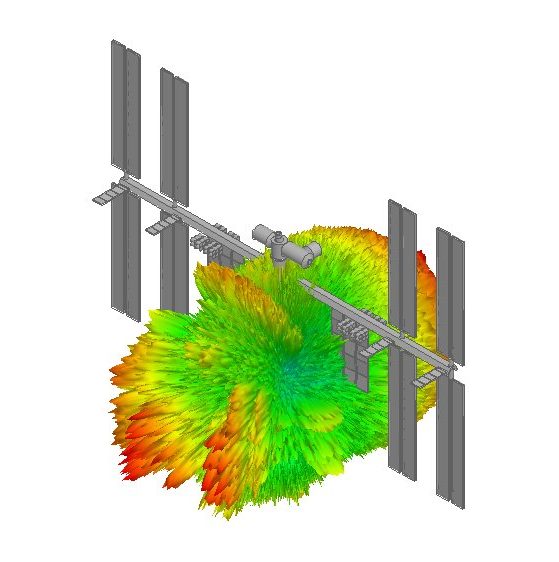
Engineers may use advanced unit cell simulation in Ansys HFSS to model infinite and finite phased-array antennas.  This includes all electromagnetic effects, such as mutual coupling, array lattice definition, finite array edge effects, dummy components, and element blanking.

In addition, under any beam scan situation, a candidate array design may analyze the input impedances of all components. Based on element match (passive or driven) far-field and near-field pattern behavior over any scan condition of interest, phased array antennas can be optimized for performance.  That is, at the element, subarray, or complete array stage.

Infinite Array Modeling

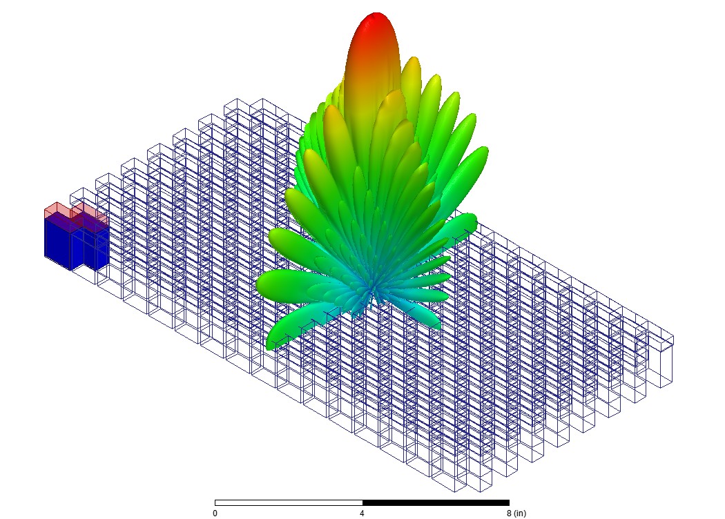
For conditional settings, one or more antenna elements are mounted inside a unit cell frequency in infinite array modeling. To create an infinite number of elements, the cell includes periodic boundary conditions on the surrounding walls to mirror fields.  Fortunately, this method is particularly useful for predicting array-blind scan angles, which may occur when array beam steering is used.

In short, this technology enables full array analysis, which includes the prediction of all mutual coupling, scan impedance, element patterns, array patterns, and array edge effects.

SI Circuits, when combined with HFSS, can be used to analyze signal integrity and power integrity.  In addition, EMI issues in PCBs, electronic packages, connectors, and other complex electronic interconnects, caused by shrinking timing and noise margins.

From die-to-die across ICs, bundles, connectors, and PCBs, HFSS with SI Circuits can handle the complexities of modern interconnect design. Engineers can understand the performance of high-speed electronic products well before constructing a prototype in hardware, saving time and money.  By leveraging the HFSS advanced electromagnetic field simulation capability, dynamically integrated at the circuit and device level, engineers have complete control over the design process.

Circuits and RF systems simulation technologies, when combined with HFSS, construct an end-to-end high-performance workflow for RF, EMI/EMC, and other applications.

EMIT, a multi-fidelity method for predicting RF device output in complex RF environments with multiple sources of interference, is included. EMIT also includes diagnostic tools for easily identifying root-cause RFI issues and resolving issues early in the design process.

Ansys Electronics Software