New elements of the latest update include the quadrilateral low-order 4-node SOLID272 and high-order 8-node SOLID273 general axisymmetric elements. The related surface effect element SURF159 was included to augment the loads that could be considered for structural software, and is user-set to include or exclude midside nodes. These new elements permit users to create axisymmetric models that, unlike older harmonic elements, consider non-axisymmetric loads while including nonlinear behaviors (contact, material nonlinearity, and large displacement).
Users set the “Number of Fourier nodes in the circumferential direction” (the number of nodal planes), with a higher number to achieve greater accuracy with non-axisymmetric loading. The number of elements remains that number meshed onto a 2D plane, while the number of nodes is dependent on the number of nodal planes—up to twelve. This can permit more efficient modeling of axisymmetric structures subject to axisymmetric or non-axisymmetric loading, including torsion, with or without nonlinearities present.
These 2D solid elements are meshed onto a positive half-plane (master plane) and describe the cross-section of an axisymmetric structural FEA model. After initial 2D solid element meshing, a coating of SURF159 line elements may be applied to exterior element faces that are to receive special pressure loading.
Quoting selected portions of the Element Reference manual at Ansys v14.0:
4.1.1.5. General Axisymmetric
General axisymmetric is the same as axisymmetric except that the deformations can be nonaxisymmetric.
Ansys recommends using the SOLID272 and SOLID273 elements to simulate general axisymmetric characteristics. The general axisymmetric elements offer the following benefits:
Note the possibility of choosing any axis as the axis of symmetry, not just the global X-Y plane:
4.1.5.1. General Axisymmetric Elements
Different from harmonic axisymmetric elements, general axisymmetric elements (SOLID272, SOLID273, and SURF159) introduce the Fourier series into the interpolation functions to describe the change of displacements in the circumferential (θ) direction. The elements can therefore apply to any analysis type, including geometric nonlinear analyses, and can support any load and deformation mode. For more information, see SOLID272 – General Axisymmetric Solid with 4 Base Nodes and SOLID273 – General Axisymmetric Solid with 8 Base Nodes in the Mechanical APDL Theory Reference.
The elements can have any axis as the axisymmetric axis (defined via SECTYPE and SECDATA commands). You need only define base elements on a flat plane.
Definitions follow in the Element Reference manual:
General Axisymmetric Element Terminology
The plane on which quadrilaterals or triangles are defined is called the master plane. The quadrilaterals, triangles, or lines on the master plane are called base elements, and the nodes of the quadrilaterals, triangles, and lines are called base nodes.
A nodal plane (copied from the master plane) is a radial plane of Fourier nodes. There are n nodal planes (where KEYOPT(2) = n), equally spaced around the circumference.
An integration plane is a plane which sits equally between any two adjacent nodal planes. Integration points in the circumferential direction are located on both the nodal and integration planes. For more information, see SOLID272 – General Axisymmetric Solid with 4 Base Nodes in the Mechanical APDL Theory Reference.
After creating the base elements and desired surface effect elements, nodal planes are created around the model axis with the NAXIS command:
The NAXIS command automatically creates a full 3-D finite-element model using the base elements, the axisymmetric axis, and the number of Fourier nodes specified via KEYOPT(2). The axisymmetric axis must be on the master plane, and the base elements must be on one side of the axis. A base element or base node must be associated with one axisymmetric axis before issuing the NAXIS command. All generated nodes are equally distributed circumferentially.
The default element coordinate system is a cylindrical coordinate system having the axisymmetric axis as z, the origin defined via the SECDATA command, and θ = 0 at the master plane. The right-hand rule determines the direction of θ, resulting in x(r), y(θ), and z from the right-hand coordinate system…
Use of the SOLID172 element with a partial coating of SURF159 elements will be illustrated next. This should clarify some of the information implied above, and detail some of the settings of element options, real constants, the NAXIS command and section definitions that make the use of these general axisymmetric elements possible.
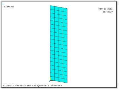
The SOLID272 and SOLID273 elements initially appear as 2D elements meshed onto the base plane. In Figure 2 below, a mesh of SOLID273 elements has been meshed onto a rectangle placed on the global X-Y plane. The intended axis of revolution in this example is the Global Y axis, but since any axis could be used with these element types, the SECTYPE and SECDATA commands will be used to indicate what axis is wanted.
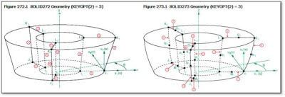
The images of the SOLID272 and SOLID273 elements in the Element Reference show a single element after the NAXIS command has generated 3 nodal planes. Three nodal planes are generated if KEYOPT(2) for the element type is set to the value “3”. Note the presence of a midside node in each nodal plane when SOLID273 is used:
Other Element Reference manual comments explain further details. Note that the newer general axisymmetric elements may be easier for users to employ than the older harmonic axisymmetric elements. Quoting again:
The displacements in the r, θ, and z directions, however, are interpolated by
ui = hi(s,t)(c1 + a1cosθ + b1sinθ + a2cos2θ + b2sin2θ + a3cos3θ + b3sin3θ . . .)
where
i = r, θ, z
and
hi(s,t) is the standard interpolation function for 2-D elements.
The nodes can have their own coordinate systems defined in any direction, as is the case with the nodes of any other solid element. For more detailed information, see General Axisymmetric Solids in the Mechanical APDL Theory Reference.
General axisymmetric elements differ from harmonic axisymmetric elements in that you do not specify the symmetric and unsymmetric terms, input peak values of loads, and solve for each term as one load step. Instead, you apply all physical loads (forces and displacements) at the nodes and solve the problem only once to obtain the solution.
The order of hi(s,t) is determined by the element type. (SOLID272 is a lower-order element and SOLID273 is a higher-order element.) The order of Fourier terms is determined by the number of Fourier nodes, or the number of nodes created in the circumferential direction for one base node (including the base node itself). This number is also the number of nodal planes in the circumferential direction, which you input via the element’s KEYOPT(2)…
The Element Reference gives some more information before providing an example. Note that if the detail required in the circumferential direction is too great for 12 nodal planes, users should consider a fully 3D solid model:
For KEYOPT(2) = 1, the deformation is also axisymmetric but, unlike the axisymmetric option of 2-D elements such as PLANE182, the general axisymmetric elements allow torsion. If no torsion load exists, it is more efficient to use the axisymmetric elements.
To simulate unsymmetric deformation, set KEYOPT(2) > 1. The greater the number of Fourier nodes, the more accurate the simulation of complicated deformation modes.
Solve localized deformation problems with a greater number of Fourier nodes (higher-order Fourier terms). Be aware that the deformation is not as localized as it would be when using standard 3-D solid elements; with general axisymmetric elements, displacements are interpolated using Fourier terms in the circumferential direction (rather than being interpolated piecewise using linear/quadratic functions as in 3-D solid elements).
Contact is usually a local phenomenon. Generally, higher-order Fourier terms are necessary.
The maximum allowed number of Fourier nodes is 12. If more than 12 nodes are necessary, a general axisymmetric element may not be computationally efficient; therefore, it is better to use a standard 3-D solid element for such cases.
For more information, consult the Element Reference section:
// Element Reference // 4. Elements for Stress Analysis // 4.1. Continuum Stress Elements
Follow the links in the above section for related information.
For the mesh, SECTYPE defines section type 1 to be an axis. The SECDATA command data is based on the most recent SECTYPE command, and “Pattern 2” defines the axis from a coordinate system number plus an axis choice where 1=X, 2=Y and 3=Z, and the coordinate system must be Cartesian. The number of nodal planes = nplane …
et,1,272 ! element type “1” is SOLID272 4-node gen. axisymmetric
keyopt,1,2,nplane ! enough fourier nodes in the circumferential direction
TYPE,1 ! global attribute for element type for meshing
sectype,1,axis ! section type 1 to be axis of general axisymmetric section
secdata,2,0,2 ! locate axisymmetric axis, “Pattern 2”, CSYS=0, 2=Y axis
SECNUM,1 ! global attribute for elements to be created
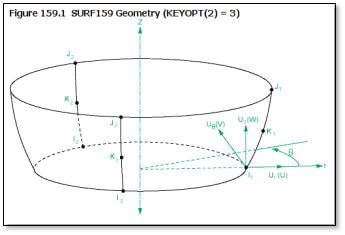
Before using the NAXIS command to create layers of Nodal planes in the circumferential direction, a coating of SURF159 elements will be created on regions that have specialized surface loads. In the figure below we see the SURF159 line element with a 3-node option (a midside node so that it can curve and fit over a face on a high-order SOLID273 element), after the NAXIS command moves it through 3 nodal planes in the circumferential direction.
The following commands define a SURF159 element type for a 2-node application, intended for surface pressure:
ET,5,SURF159
KEYOPT,5,2,nplane ! Number of Fourier nodes.
KEYOPT,5,3,0 ! Pressure appl to faces 1 through 3K (3xKEYOPT(2)) per coord sys:
! 0 = Apply face loads in the default element coordinate system,
! for example, the first K faces act normal to the surface
! 1 = Apply face loads in the specified element coordinate system
! for example, the first K faces act in the x direction as
! defined via the ESYS attribute
KEYOPT,5,4,1 ! NO midside nodes
KEYOPT,5,6,0 ! use pressures as calculated (positive & negative)
KEYOPT,5,7,0 ! use new area if large deflection
KEYOPT,5,11,2 ! 2 = on FULL area and included tangential component
KEYOPT,5,12,0 ! pressure load regardless of element norm orientation
r,5 ! real constant for SURF159
rmodif,5,7,1.0e-6,1.0e-6 ! In-plane thickness at node I and J.
! ETABLE volume will return SURF159 area factored down by 1.0e-6
mp,dens,5,0.0 ! zero mass for SURF159
The ESURF command will create the coating of SURF159 elements.
In the above commands, “In-plane thickness at node I and J” was applied. This was for postprocessing so that an ETABLE element table column can generate the SURF159 element volumes, from which their area can be measured by dividing the SSUM value of the volumes by the assigned thickness. A zero density material property was assigned so these SURF159 elements do not add mass to the model. In the present example, SURF159 elements apply internal pressure in the cylinder, so KEYOPT(11) applies pressure over the full area, and KEYOPT(12) applies pressure regardless of element orientation. A real constant attribute was assigned globally by the R command. Use of a midside node is either set or not set according to underlying SOLID273 or SOLID272 element use.
With the above commands executed, the NAXIS command can generate the 3D model that is implied by the general axisymmetric elements. The /ESHAPE,1 command in PowerGraphics lets ANSYS plot the 3D view of these general axisymmetric elements:
naxis,gen ! generate nodes around the axis, number=KEYOPT(2) value
allsel
/eshape,1 ! make 3D solid view of elements possible
/view,1,1,1,1 ! isometric view
eplo ! plot elements
Once NAXIS has been executed, the SURF159 elements can have pressure applied, for example:
esel,s,type,,5 ! select the surface effect elements of interest
nsle ! select their nodes
SF,all,PRES,pr ! pressure normal to face, applied to selected nodes
allsel
In the above example of ordinary normal pressure with numerical value “pr”, the SF command has been used, rather than the SFE command in which face choices must be considered carefully with SURF159 surface effect elements. To apply shear or other non-perpendicular loading to SURF159 elements, the SFE command with face number references is required. Users should see the Elements Reference for SURF159 for more information.
After the NAXIS command is applied, some external loads on exterior surfaces can be applied with a surface-based constraint. For this purpose, a TARGE170 pilot node is associated with a set of CONTA175 contact elements that coat a chosen surface on the SOLID272 or SOLID273 elements after the NAXIS command is applied. The CONTA173 and CONTA174 elements cannot be used with these general axisymmetric elements, because after NAXIS, general axisymmetric solid element faces are neither 4-noded nor 8-noded.
In brief testing, a force-distributed surface-based constraint has successfully applied a shear load to a flat face on the end of a cylindrical pipe modeled with general axisymmetric elements, however, a moment loading with the moment vector in the plane of the flat face produced local stress spikes when the contact surface was set to flexible (force-distributed with KEYOPT(4) for CONTA175 set to “1”). NOTE: The Elements Reference says that KEYOPT(4)=1 for flexibility is NOT supported in surface-based constraints with these general axisymmetric elements. Instead, the following rigid settings were used in further testing with a moment vector in the plane of the flat face. Degree of freedom settings for the pilot node were chosen to keep the face flat, controlling node movement perpendicular to the flat face, while permitting node movement in the flat plane. In this simple example, the flat plane was located in the global X-Z plane, and the applied moment was about the Z axis. Pilot node degrees of freedom for constraint were those that cause out-of-plane node movements by the CONTA175 elements (ROTZ, ROTX and UY). In more complex models, nodal coordinate systems could be adjusted to get this effect.
The following commands create a keypoint located where a TARGE170 pilot node is wanted, and coat an associated flat face on a model with CONTA175 elements. The surface behavior is set to Rigid. Only degrees of freedom at the TARGE170 pilot node are chosen that cause out-of-plane contact surface movement. This prevents localized stress spikes seen if the surface is set Flexible (which is not supported by ANSYS). This approach appears to support moment vectors that lie in the plane of the flat face, and might similarly work with force perpendicular to the flat face. It does not support other moments or forces. Not including in-plane node movements in the degrees of freedom of the TARGE170 pilot node permits thermal expansion and expansions due to internal pressure. In the following example, component “n_272” refers to a set of nodes where the surface-based constraint is applied:
! Prepare to apply a load via a surface-based constraint
! Use CONTA175 elements, not CONTA174 on SOLID272 & SOLID273
!
k,1000,0,height,0 ! create an independent keypoint at the top
!
/COM, CONTACT PAIR CREATION – START
MAT,3 ! coordinate MAT with REAL (not used)
R,3 ! use REAL 3 for contact pair
REAL,3 ! global attribute
ET,2,170 ! TARGE170 for pilot node where load is applied
ET,3,175 ! CONTA175 for surface on solid model
KEYOPT,3,12,5 ! Bonded always contact
!
KEYOPT,3,4,0 ! RIGID at contact surface
!
KEYOPT,3,2,2 ! Multipoint constraint at contact
KEYOPT,2,2,1 ! TARGE170 BC for target specified by user
KEYOPT,2,4,101010 ! TARGE170 ROTZ, ROTX, UY
!
TYPE,2
! Create a pilot node
KSEL,S,,,1000 ! the free keypoint created above
KATT,3,3,2,0 ! attribute mat, real, type, esys
KMESH,1000 ! create pilot node from TARGE170
!
! Generate the contact surface
cmsel,s,n_272 ! nodes on the SOLID272 elements
nsel,r,loc,y,height ! top layer of the nodes
!
TYPE,3 ! type is CONTA175
ESLN,S,0 ! SOLID272 elements touching these nodes
ESURF ! coating of CONTA175 elements
!
allsel
/com, End of contact pair creation
Note above, KEYOPT(4) for the CONTA175 element type chooses rigid behavior at the contact surface, while for the TARGE170 element type, KEYOPT(2) chooses user-specified degrees of freedom, and KEYOPT(4) indicates use of “ROTZ, ROTX, UY” which for a surface in the X-Z plane implies Y-direction CONTA175 element node movements only. Because in-plane CONTA175 element node movements are not affected, thermal expansion and in-plane pressure-induced node movements are still possible. A flexible force-distributed surface-based constraint would be ideal, but ANSYS states NOT supported, and since when tried stress spikes were encountered with moment loads and SOLID272 and SOLID273 elements (it worked properly with SOLID186), the rigid approach has been employed.
A simple test model was created with SOLID272 general axisymmetric elements. The axis for this model was set to be the Y axis. Element types for SOLID272 and low-order SURF159 were created with KEYOPT(2) set to 12 nodal planes. A rectangle on the X-Y plane was meshed with SOLID272, the inner edge of the rectangle was coated with SURF159 elements, and the NAXIS command generated the nodal planes. The /ESHAPE,1 command was executed, and a 3D view of the resulting model was possible.
A surface-based constraint was applied to the top face of the cylinder, with a TARGE170 pilot node at the center of the circle at the top, and CONTA175 node-to-surface contact elements meshed on the nodes of the top face via the ESURF command. If only a shear force was to be applied to the pilot node for the top face, a flexible force-distributed surface-based constraint might have been satisfactory (but is considered NOT supported by Ansys). When a moment was applied to the pilot node, it was found that rigid settings for the top face were required to avoid non-physical stress spikes.
With a rigid setting, only the ROTZ, ROTX and UY degrees of freedom for the TARGE170 pilot node element type were constrained, so that the nodes at the CONTA175 elements could move in the plane, permitting unconstrained thermal expansion and pressure-driven radial expansion in the plane.
The following figure shows a 3D view of the model with pressure on the inner diameter and a moment applied via a surface-based constraint at the top face.
A blue arrow shows the moment applied to a “star” located at the TARGE170 pilot node at the center of the top face. Light blue stars show the CONTA175 elements on nodes at the top of the cylinder. Red arrows show the normal pressure on the interior. This example has 12 nodal planes:
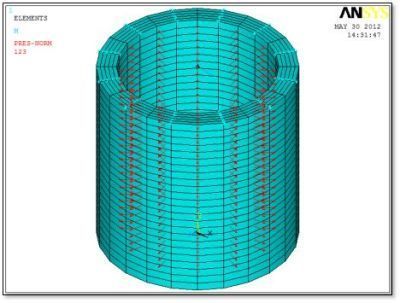
The bottom face has perpendicular constraints in the Y direction, and enough X and Z constraints to prevent motion in the X-Z plane while permitting radial expansion. If the above model is run with only an internal pressure applied, it expands as expected in the radial direction. If it is run with moment but no internal pressure, then bending deformation and pure bending stress are seen.
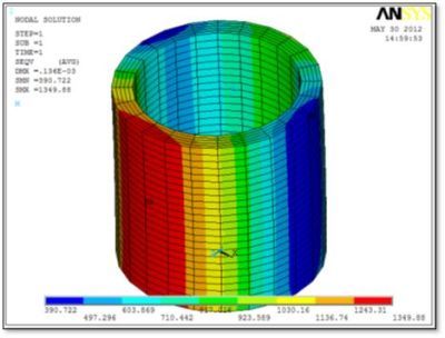
In the figure below we see stresses due to combined bending and internal pressure. The SURF159 elements were unselected before generating the stress and deflection plots because they do not indicate any stress, and they do not move in space when plotted.
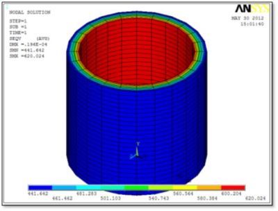
Next, we see stress due to internal pressure only, with the end moment removed. Stresses are symmetrically distributed, as expected, if minimal constraint is used on the bottom face:
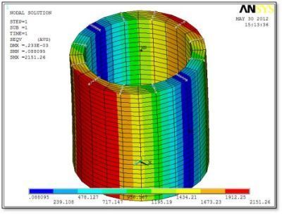
Now, in this figure, we see stresses under pure bending. Boundary conditions at the bottom face were adjusted slightly, to use a minimum number of nodes to prevent in-plane movements.
General axisymmetric elements, the 4-node low-order SOLID272, the 8-node high-order SOLID273, and the associated SURF159 surface effect element, can be used for axisymmetric models with non-axisymmetric loads, with simpler setup for the user in comparison to harmonic axisymmetric elements, and support for nonlinear effects including contact with conventional 3D solid elements.
The number of nodal planes for these elements is controlled by KEYOPT(2) for the element types. Values for the number of nodal planes for the solid and surface effect elements that work together must be coordinated before the NAXIS command is applied.
Users should note that the Ansys Manuals comment that if the model is so complex that 12 nodal planes with SOLID273 elements do not provide sufficient resolution, then solid elements such as SOLID186 should be considered for modeling.
With a finite number of nodal planes, approximation of degree of freedom movements around the circumferential direction may result in nodal forces or reactions not seen in a model made from SOLID186 elements.
The general axisymmetric elements support contact with standard 3D elements. CONTA175 node-to-surface contact elements are used on faces of the general axisymmetric elements, while TARGE170 surface contact elements are used on the standard 3D elements for a contact pair.
In addition, users should be aware of the following from Ansys, quoted from the Elements Reference. Note limitations on force-distributed surface-based constraints, and not using KEYOPT(4)=1 which would request a flexible surface.
These restrictions do not state explicitly that a rigid surface-based constraint is supported. In limited testing, rigid behavior settings with ROTZ, ROTX, and UY degrees of freedom, as mentioned in this article, did yield a response that did not include stress spikes. Users may prefer to apply surface loading with pressures on SURF159 elements.
Users learning to use these general axisymmetric elements are advised to work with small simple test models, and to see that their results match those of models created with 3D solid models and closed-form solutions, before considering complex real-world models. Guidance contained in this article is of the “use at your own risk” type.
As usual, model verification should include checks on displacement, stress, and reaction forces, as well as comparison with hand calculations, 3D solid model FEA behavior, and expectations based on experience. The Ansys written materials on these elements and this approach to non-axisymmetric modeling should also be studied in detail.
The latest Ansys Software releases to support with force on a construction geometry surface
Ansys Mechanical Workbench is a top-tier finite element solver with capabilities to enhance your modeling in the areas of structural, thermal, acoustical, transient, and nonlinear behavior.
Ansys LS-DYNA simulates the response of materials to short duration severe loading. Today, it is the single most used explicit dynamics simulation program worldwide. Best suited for highly technical users.
Ansys EnSight is the market leader for data visualization. Its post-processing tool includes models with more than hundreds of millions of cells, providing engineers with insights unavailable elsewhere.
Ansys Motor-CAD is a specialized electric machine design tool that allows for quick multiphysics simulation over the entire torque-speed working range.
Ansys HFSS simulates 3-Dimensional full-wave electromagnetic fields for accurate and rapid design of high-frequency and high-speed electronic components.
Gain quick, accurate electronic hardware life predictions with Ansys Sherlock, the only PoF (Reliability Physics/Physics of Failure) software that provides insight at each the system, board, and component levels.
A comprehensive solution for designers, engineers, and analysts that spans the full workflow, from design for additive manufacturing (DfAM) to validation, process simulation, and material exploration
Component-level and system-level simulations are provided by the extensive range of photonics simulation to improve performance, lower the price of physical prototyping, and shorten time-to-market.
Ansys Icepak provides specialized electronic cooling solutions that utilize the industry leading CFD solver for T&F flow analyses of integrated circuits, PCBs and electronics.