Webinar Description:
This webinar will explore various ways of designing bolted connections and discuss the pros and cons of each method.
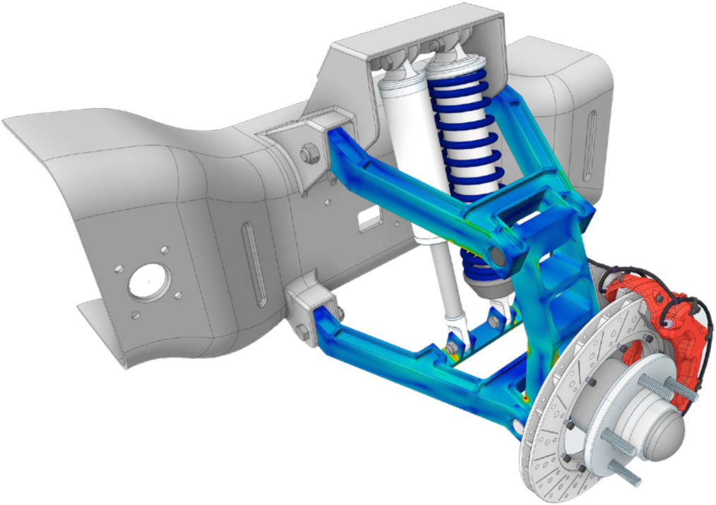
Bolt Pretension & Contact Options
Topics include using beam elements to model bolts, contact options for bolted connections, and ways to apply bolt pretension.
Access the Webinar
Concept and Formulas for Bolted Connection Design
A type of structural joint known as a bolted connection uses bolts to link two or more structural components of a steel structure. A type of threaded fastener known as a bolt has a male thread and a preformed, complementary female thread, similar to nuts. To build a bolted connection, it is crucial to understand the bolt value and joint strength concepts, which are further explored.
Joint Types in Bolted Connections
In a bolted connection, the lap joint and butt joint are the two most common types of joints. Within these two types, there exist sub-types like quirky connections and pure moment connections, but those are outside the purview of this site.
The following explanations describe the sub-types of joints and their nature.
Lap Joint
In a lap joint, the major connecting elements are positioned on top of one another to create an overlap, and the overlapping area is then bolted. An eccentricity is created as a result of the relationship itself.
Butt Joint
A cover plate is used to link two pieces in this kind of joint. There are two types of butt joints: single cover butt joints and double cover butt joints, based on the number of cover plates.
Choose this on-demand webinar, Designing Bolted Connections, to learn more about bolts. Including, different types of bolts, and other sorts of butt and lap joints.
Bolted Connection & Most-Preferred Joints
The double cover butt joint is the most popular of the aforementioned joints for the reasons listed below.
- The bolt’s shear capability exceeds that of a lap joint.
- There is no eccentricity in the link.
Types of Bolted Connection Failure
Either the connecting plate or the bolt could fail in a fastened connection. It is crucial to take into account the “Limit States” or failure mechanisms of both the bolt and the plate as a result.
The following list includes potential limit states via which a bolted connection could fail.
Bolt Failure Modes in a Bolted Connection
- Shear Bolt Failure
- Bolts with Bearing Failure
- Bolt Tensile Failure
Additional Ansys Software Tips & Tricks Resources
-
- Analyzing normal and Tangential Elastic Foundations in Mechanical
- Why Meshing is Crucial for FEA Fluid Simulations Prior to Prototyping
- For support on Contained Fluid FEA Modeling with HSFLD242 Elements
- For Exporting a Deformed Geometry Shape Post-Analysis in Mechanical
- Moreover, for guidance Multi-Step Analyses in Mechanical
- For Retrieving Beam Reaction Force in a Random Vibration Analysis
- Deploying Ansys Macro Programming vis *USE Command in Mechanical
- For replicating Fatigue Models from Start to Finish in Mechanical
- In addition, setting up Acoustic Simulations of a Silencer
- For a step-by-step guide on 2D to 3D Submodeling in Mechanical
- For modeling Pipe16 Circumferential Stress in Mechanical
- For Support on performing ‘EKILL‘ in Workbench
- APDL Command Objects post-Spectral Analysis
- For Separating DB Database Files from RST Files
- Measuring Geometric Rotation in Mechanical WB
- Explicitly, CAD Geometry Deformation Plasticity
- Offsetting a Temperature Result to Degrees Absolute
- For general guidance on Ansys Post-Processing
- Finally, for basic Ansys Software Installation and License Manager Updates