Strain Gage Responsiveness | Thermal Output
Constantan and modified Karma strain gage alloys must both have the ability to respond to particular processing for self-temperature correction.
Self-regulating strain gages are made to provide the least amount of thermal output (temperature-induced apparent strain) over a temperature range of around –50° to +400°F (–45° to +200°C).
The self-temperature-compensation (S-T-C) number must be given when selecting either constantan (A-alloy) or modified Karma (K-alloy) strain gages. The S-T-C value is the structural material’s approximate thermal expansion coefficient in ppm/°F on which the strain gage will produce the least amount of heat.

Uncompensated Isoelastic Alloy
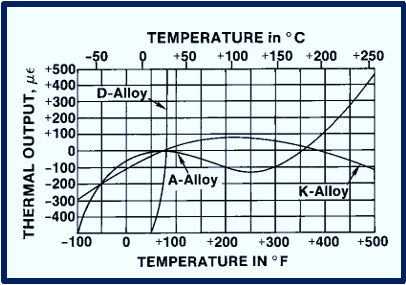
Typical heat output characteristics for A and K alloys are shown in the graph to the right.
For comparison, the thermal output of an uncompensated isoelastic alloy is given in the same output range.
In most cases, the S-T-C value for an A- or K-alloy gage is chosen to match the test material’s thermal expansion coefficient as precisely as possible.
General Thermal Output Characteristics | Strain Gage Alloys
Clockwise Thermal Output Curve
The thermal output curves for these alloys, on the other hand, can be adjusted around the room-temperature reference point to favor a specific temperature range.
This is accomplished by deliberately mismatching the S-T-C number and the expansion coefficient in the desired direction.
The curve is spun counterclockwise when the selected S-T-C number is less than the expansion coefficient. The thermal output curve rotates clockwise when there is an opposing mismatch.
Calibrating Installation for Thermal Output
The thermal output curves for A and K alloys do not apply in conditions of S-T-C mismatch, of course. In addition, it will be necessary to calibrate the installation for thermal output as a function of temperature.
However, when choosing a grid material, other features of D alloy should be taken into account. If is magneto-resistive, for example, and its reaction to strain is nonlinear, increasing notably so at strains beyond 5000 με.
Karma Alloy | Strain Gage Thermal Properties
Now, we journey away from Isoelastic alloys and venture into Karma (K).
Altered Karma, or K alloy, is a significant member of the family of strain gage alloys due to the wide range of applications it has.
This alloy is the preferred option for reliable static strain measurements over long periods of time (months or years) at room temperature, or shorter periods at increased temperature. It is distinguished by good fatigue life and great stability.
For prolonged static strain measurements in the temperature range of –269 to +260°C (–452 to +500°F), it is advised. Encapsulated K-alloy strain gages can be exposed to temperatures as high as +750°F (+400°C) for brief periods of time. The stability and useable gage life at high temperatures will both be enhanced by an inert environment.
Flatter Thermal Output Curves
Along with other benefits, K alloy has a thermal output curve that is substantially flatter than A alloy’s, allowing for more precise rectification of thermal output mistakes at high temperatures.
K alloy, like constantan, can be used on materials with various thermal expansion coefficients by self-temperature compensating for temperature.
However, there are only a few S-T-C numbers that are accessible in K alloy: 00, 03, 05, 06, 09, 13, and 15. When a temperature-compensated gage is needed with environmental capabilities and performance qualities that are not possible with A-alloy gages, K alloy is the typical choice.
Opened-Faced K-alloy Gages & Duplex Copper Padding
The duplex copper feature, a testing option for open-faced strain gages made with K alloy, is a must have for those in modern-day environments due to the difficulties of soldering directly to K alloy.
Depending on the available tab space, the duplex copper addendums offered by manufacturers is an ideal copper soldering pad (DP) or dot (DD) specifically designed for stain gage testing. All K-alloy gauges without leads or solder dots are identified by the designations DP or DD (in place of, or in addition to, the option specifier).
When North American clients contact our Mechanical Testing Engineers, the exact style of copper treatment will be ordered, to ensure accuracy and a 1:1 replication testing environment.
Related Strain Gage Engineering Articles

How to Choose the Correct Strain Gage for Testing
Strain Gauge selection may appear to be a simple task with little significance for the stress analysis, but this is far from the case. Learn why.
What are the different types of Strain-Sensitive Alloys?
The strain-sensitive alloy employed in the foil grid is critical in determining a strain gage’s working properties. Learn the benefits and utility of each alloy type.
What Backing Materials are Used in Strain Gages?
Strain gages come with two types of backing materials, along with corresponding alloy combinations, unique manufacturing features, and created as micro-systems.
Determine the Optimal Gage System, or Series
So, you’ve determine a need for strain gage testing. Now, a choice must be made via available gage systems, each of which includes unique design features and construction aspects.
Recommended Gages for Specific Test Profiles
Considerations for the Strain Gage Series selected must include that of specific test profiles, such as strain type, operating temperature, measurements duration, and more.
Best Practices when Selecting Gage Length
When possible, the gage length should be no more than 0.1 times the radius of a hole, fillet, notch, or corresponding dimension of any other stress raiser. Learn why.
Application of Strain Gage Pattern Analysis & Testing
Strain gages are ideal for verifying stress and displacement simulation models. The strain measurements are taken at specific locations and correlated with the optimal strain gage pattern orientation, and general testing protocols determined via reiterative simulation results.
Modeling assumptions such as boundary conditions, contacts, and loads may be updated to make the simulation better fit the observed behavior.
Once the model accurately reflects the measurements, more detailed information about the system can be inferred.
In addition, simulations of the modified system can be used to predict behavior with confidence.
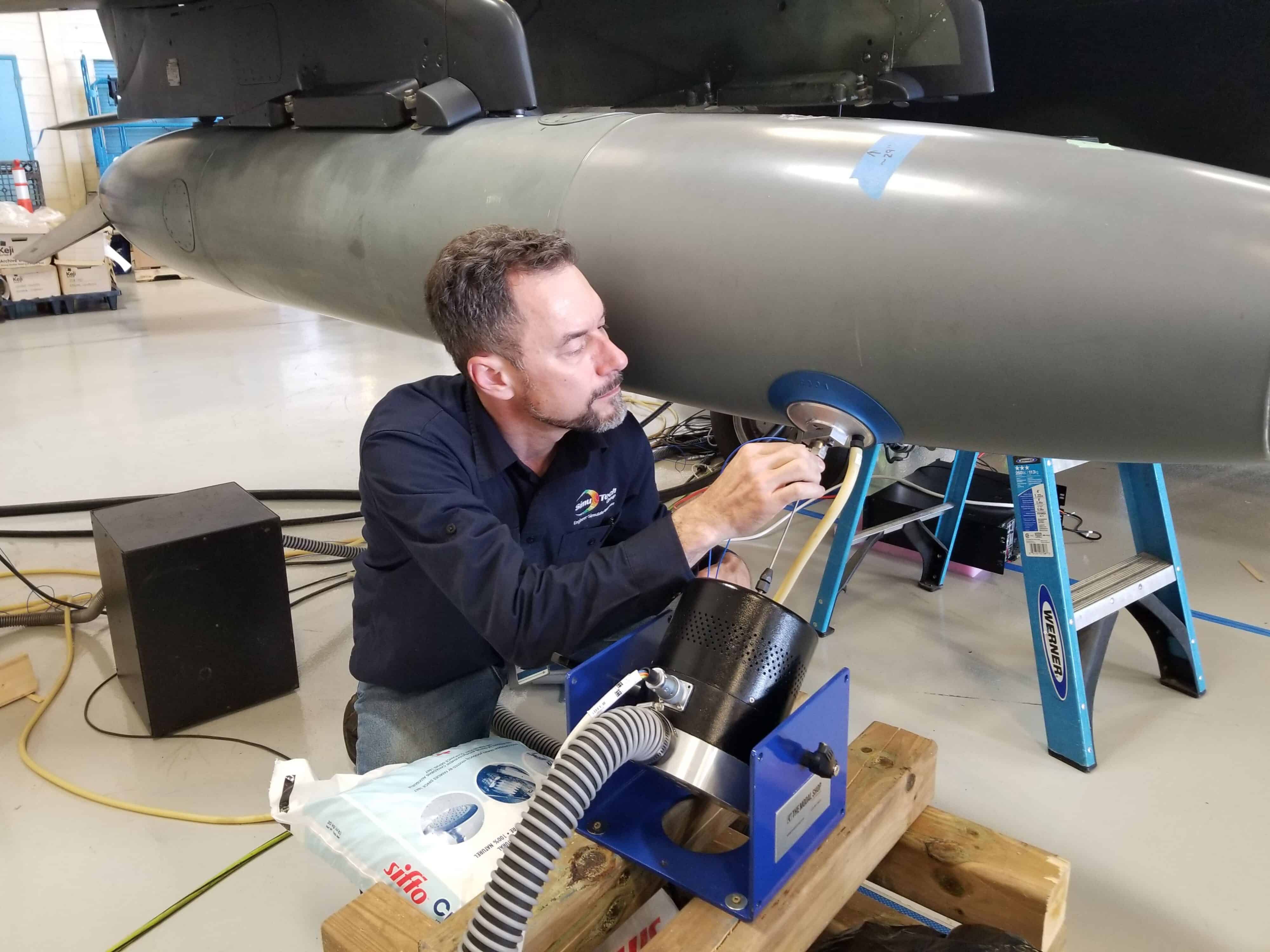
SimuTech Group specializes in both strain gage measurement as well as simulation, allowing seamless support when conducting investigations.
Contact for Strain Gage Testing Services
Additional Mechanical Testing Services Offered
Turbine Blade Frequency
For new, refurbished, or reverse engineered turbine blades (buckets) to ensure that natural frequencies are within specifications.
Torsional Vibration
Determine the natural frequencies and mode shapes of a rotor train as it twists about the axis of rotation.
Vibration Diagnostics
Identify the root cause of noise and vibration problems in machinery via ODS, spectral, order tracking or joint time frequency analysis.