What is GUI in ANSYS?
Ansys pours a lot of resources into creating the very powerful software products that have become an integral part of our engineering world today. However, with the wide spectrum of users, companies, and industries utilizing these products are used, it is impossible to provide a tool that does everything which all users might want it to. Inevitably, individual users have their own preferred methods of working.
Companies often have their own standardized procedures too. So what does one do when the available tools don’t have desired features/functionality to allow the best workflow for you or your company? Software enhancement requests send ideas from the users back to the developers, but macros of some form or another can often be a better solution because the end user doesn’t have to consider the needs/constraints of other users, companies, or industries.
Users of the Mechanical APDL interface (aka Ansys Classic) have been writing macros for decades. The APDL code these macros are written in is straightforward and well documented. Users of the Workbench interface aren’t quite so well off. Ansys 13.0 provides some pretty good documentation regarding scripting of the project schematic using Python, and eventually this type of scripting will be available in Mechanical. But right now, macros which might run in the Mechanical application are not documented at all. The good news is that while there is no formal documentation for creating macros to run within the Mechanical interface, there is a methodology that allows a motivated user to write macro code.
This article is not intended to be even an introductory training to writing macros for Mechanical, but to merely show some of the basic concepts, illustrate what is possible, and hopefully plant ideas about how macros could make your analysis life even easier. The interested reader is encouraged to contact SimuTech for further information on personalized instruction or contract work in this area.
The Basics | Mechanical GUI
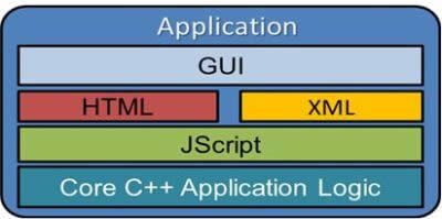
The Mechanical GUI is built by JScript from HTML and XML files which define things like menus and toolbars. User input is captured by JScript which then calls the core C++ application functions. When the user clicks Solve, the Mechanical application creates a text based APDL input file which is then submitted in batch mode to the solver. So if we wish to automate something in the Mechanical GUI, we’ll need to use JScript. (If we wanted to automate something at the solver level, we’d use APDL in a Command object.)
Ansys already ships with a number of predefined macros that are found in C:\Program Files\Ansys Inc\v130\aisol\DesignSpace\DSPages\macros. One is called select BySize.js, and it will loop over all the geometry in your model and select the same type of geometry items of similar size. So if you select a face, then choose Tools >> Run Macro and pick this file, the macro will automatically find and select all other faces in your model whose surface area is equal to the face you have selected. Very useful if you needed to select say 100+ faces representing washer faces. (Note: this same type of selecting can now be accomplished in 13.0 with criteria based Named Selections that do not require running a macro.)
Now we understand a few things about macros which run in the Mechanical interface:
- They are programmed in Jscript
- A number already exist and ship with the code
- They are run via Tools >> Run Macro
JScript
The GUI programming language for the Mechanical/Meshing applications as well as DesignModeler is JScript. JScript is Microsoft’s implementation of JavaScript which adds some Windows specific capabilities. JavaScript itself is an interpreted programming language originally built for use on Web pages. The syntax of JScript is similar to C and Java (but JScript is NOT the same as Java). Basic JScript information and resources are plentiful and a good place to start is W3Schools.
Techniques
While it is not difficult to learn basic JScript we need to know how to use it within the Ansys Mechanical GUI. We can go looking in the *.js files in the aforementioned \macros directory but this won’t get us very far beyond perhaps understanding how each macro works.
We can also go looking in the *.xml files which create the Mechanical GUI to see what internal functions are being called when a button or menu is clicked. Many of these functions are defined the .js files found in:
C:\Program Files\Ansys Inc\v130\aisol\DesignSpace\DSPages\scripts
Beyond this we need to attach a debugger to the Mechanical GUI process and look inside the code while it is running. Microsoft Office ships with something called the Script Editor which is a sort of poor-man’s debugger. While this will work, a better option is the proper debugger in Microsoft Visual Studio. In addition to having a debugger installed, the following registry setting must be in place:
HKEY_CURRENT_USER > Software > Microsoft > Windows Script> Settings>JITDebug = 1
Once a debugger is installed, the Just-In-Time Debug registry key set properly, and a good text editor with directory search capabilities is at hand, we are ready to do something useful…
How to Write a Macro in Ansys Mechanical Workbench | Practical Use-Case
To illustrate the approach to writing a macro for Mechanical we will use a real world situation that I encountered several months ago. A consulting project required setting up several hundred Remote Points at the center of annular faces representing washers.
Now creating a RP is not difficult but creating several hundred of them is a job for a macro not a human… It would be nice if we could simply create a Named Selection of the faces (very easy using the NS criteria) and have the macro loop over each face in the NS and insert a RP for it.
The first step is to determine what happens when we click the button to insert a RP. To do this we search for the button’s text (“Remote Point”) in
C:\Program Files\Ansys Inc\v130\aisol\DesignSpace\DSPages\Language\en-us\xml\dsstringtable.xml
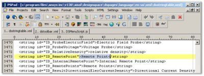
This leads us to what is called the string id for this button:
![]()
Now we search for this text, ID_RemotePoint, in all files in the directory:
C:\Program Files\ANSYS Inc\v130\aisol\DesignSpace\DSPages\xml
Defining Multiple GUI Locations in Ansys Workbench
There will be multiple hits which correspond to different files defining multiple GUI locations where this functionality can be accessed.
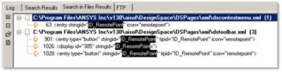
We’ll choose the dstoolbar.xml file, and look inside of it.
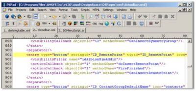
Now look for the “do…” methodName listed for the first actionCallback. And finally search for this text, doInsertRemotePoint, in all files in the directory:
C:\Program Files\ANSYS Inc\v130\aisol\DesignSpace\DSPages\scripts
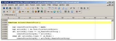
So we have figured out that if we call the function doInsertRemotePoint(), we’ll get our Remote Point. Now we need to be able to loop over the faces in a Named Selection and call this function for each one individually…
Individual Function Calls based on Named Selections in Ansys GUI
From here we need to fire up the debugger and get into the Ansys GUI code. To do this we simply create a dummy Jscript macro file with one line of code, debugger;. Assuming things are working properly, we will then be able to get into the code and go looking around. First we’ll add a “watch” to the SM object (for Selection Manager), and look at some of the methods listed:
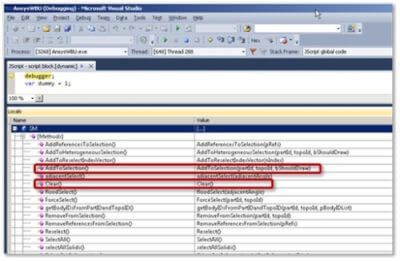
Two useful looking methods are:
- Clear()
- Takes no arguments
- Clears out the Selection Manager
- AddToSelection(partId, topoId, bShouldDraw)
- partId : an ID value for the part whose geometry is being added to the selection
- topoId : an ID value for the topology for the geometry
- bShouldDraw : boolean value determining if the selection should be drawn or not
So we have now determined two functions which will be used in a loop to first clear out the selection, then select a single face from the original Named Selection in turn. With a single face selected we can call the doInsertRemotePoint() function, then more on to the next face. The macro’s basic approach will be something like this:
1. Determine how many faces in Named Selection
2. Loop over all faces in Named Selection
a. Find partId and topoId information for each face and store this information in an array
3. Loop over the array from step 2
a. Clear out the Selection Manager : Clear()
b. Select an face : AddToSelection()
c. Call doInsertRemotePoint()
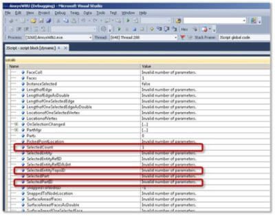
To effect the above steps we still need to do some more digging with the debugger in the Selection Manager object (SM). Some crucial things will be to determine how many entities are selected and what a given entity’s TopoID and PartID properties are.
Because this article is running a bit long already we will wrap it up by noting that while every last nitty-gritty detail of our proposed macro has not yet been figured out, the approach described forms the foundation for writing macros. Through more investigation using the debugger and some trial and error, we can come up with the final version of this macro (which is listed at the end of this article).
Next Level Ansys GUI Modifications | Jscript Macros
As mentioned before, DesignModeler uses Jscript also, so the same type of approach is valid in that application too.
And there are other things that can be done such as:
- Jscriptaddin
- Used to create custom menu and toolbar entries
- Can be used to “listen” for events such as selecting things in the outline tree or graphics window, button clicks, etc, and execute a function accordingly
- Using ActiveX objects in a macro
- Standard Windows file dialogs
- HTML dialogs to accept user input
- Interface with MS Office apps such as Excel or PowerPoint
Within Ansys GUI, here are some examples of uses I’ve found for Jscript macros:
- Setting up the APDL commands to use submodeling in Mechanical
- Loop over all Figures in the outline tree and export high resolution images for use in reports
- Select all bodies of a certain type (i.e. solid, surface, line)
- Calculate/display detailed dx/dy/dz information for the distance between two vertices
- ASLV, LSLA, KSLL equivalents from APDL
- Loop over a Named Selection and export XYZ coordinate data for the centroids of faces
- Loop over points in Design Modeler, determine closest point pairs, and create a line body between them
Caveats | Custom Jscript Programming in Ansys GUI
Since none of this Jscript stuff is documented, the developers are free to change how the code works internally and thus there is no guarantee that what works in one release will work in the next. On the flip side what isn’t possible in one release may be possible in the next!
Also, there is no official Ansys support for these endeavors, so writing macros should be approached by those who are comfortable with object oriented programming, using a debugger, and figuring stuff out on their own.
Conclusion | Creating Macros & Scripts in Ansys GUI
Hopefully this article has whetted your programming appetite for creating macros/scripts to run in Mechanical or DM within Ansys GUI. Instead of saying “I wish I could do this in Ansys…”, you now have some tools to bring those ideas to life! As mentioned before, this article was not intended to be an all encompassing introductory training document, but rather to make the user aware of what is possible and illustrate the general approach.
Appendix | Ansys Macro Loops & Error Checking
Final script listing for Ansys GUI
Below is the final code from the example mentioned in this article. It worked great for my situation and I have endeavored to make it somewhat general and include some basic error checking. However, there are no guarantees that it will work in all situations!
///////////////////////////////////////////////////////////////////////////////////////////////////////////////////////////////////////////////////////
// Macro loops over faces in a Named Selection and inserts a Remote Point for
// each one.
// Default is to use whatever NS is selected in the GUI, but the variable
// ‘cName’ may be changed to explicity specify a NS.
var SC = DS.Script;
var branch = DS.Tree.FirstActiveBranch;
if (isValidNS())
{
userFeedback(“Info”, insertRemotePointsFromNS());
}
function isValidNS()
{
var componentGroup = SC.GetNode(branch.ComponentGroup.ID);
var currObj = DS.Tree.FirstActiveObject;
var cName = “GUI” ; // Name of the component to use for adding RemotePoints
if (cName == “GUI”)<br /> { <br /> // check that active object is a NS<br /> if (currObj.Class != SC.id_Component) <br /> {<br /> userFeedback(“Error”, “Please choose a Named Selection from the outline tree”);<br /> return false;<br /> }<br /> }<br /> else<br /> {<br /> // find specified Named Selection<br /> var cCount = branch.ComponentGroup.Components.Count;<br /> var test = false;<br /> for(var i = 1; i <= cCount; i++ )<br /> {<br /> var component = branch.ComponentGroup.Components.Item(i);<br /> if (component.Name == cName)<br /> {<br /> SC.changeActiveObject(component.ID);<br /> currObj = DS.Tree.FirstActiveObject;<br /> test = true;<br /> break;<br /> }<br /> }<br /> // did not find NS specified by cName<br /> if (!test)<br /> {<br /> userFeedback(“Error”, “Could not find specified Named Selection : ” + cName);
return false;
}
}
// check NS type
if (currObj.ScopedType != SC.id_SurfaceScoping)
{
userFeedback(“Error”, “Incorrect NS type”);
return false;
}
return true;
}
function userFeedback(status, message)
{
switch (status)
{
case “Error”:
SC.wbErrorMsgBox(message,status,262144);
break;
case “Warning”:
SC.wbWarningMsgBox(message,status,262144);
break;
case “Info”:
SC.wbInfoMsgBox(message,status,262144);
break;
}
}
function insertRemotePointsFromNS()
{
SC.doTreeActivateSelection(); // select entities in NS
var numFaces = SM.SelectedCount // number of selected faces
var partIds = new Array();
var topoIds = new Array();
// loop over the selection and store partId and topoId information
for (var i = 1; i <= numFaces; i++ )
{
partIds.push(SM.SelectedPartID(i)); // store partId
topoIds.push(SM.SelectedEntityTopoID(i)); // store topoId
}
SC.changeActiveObject(branch.Model.ID); // activate Model branch
for (var i = 0; i < numFaces; i++ )
{
SM.Clear(); // clear selection
SM.AddToSelection(partIds[i], topoIds[i], false ); // add single face to selection
SC.doInsertRemotePoint(); // insert RP on selected face
}
SM.Clear();
return numFaces + ” Remote Points inserted.”;
}
///////////////////////////////////////////////////////////////////////////////////////////////////////////////////////////////////////////////////////
Contact for Additional Ansys Mechanical and/or GUI Scripting Support
Finally, we hope that you can make productive use of Ansys’ GUI, and custom Jscript and Macro’s to enhance your Mechanical models. For more information, or to request engineering expertise for a particular use-case scenario Ansys’ GUI, custom Jscript or Macro configuration, please contact us here.