Transmitting Displacement and Rotation across a Contact Pair
Ansys Workbench Mechanical permits connecting a surface body edge to the face of a flexible body to the edge of a surface body (shell) with contact elements.
If the Contact side of the contact pair is on the surface body edge, and the Target is on the flexible body face, setting MPC Bonded Contact to “Target Normal, Couple U to ROT” will transmit both displacement and rotation across the contact pair.
In effect, the edge of the surface body transmits moment and acts as if it is welded to the face of the flexible body. With recent ANSYS releases, e.g. v19.2 of Ansys, the MPC Bonded Contact works with Constraint Type set to “Program Controlled”.
If the flexible solid body is set to Rigid, the MPC bonded constraint no longer transmits rotation and moment at the node level. The connection acts like a hinge, losing the ability to act as a welded connection. Node rotation coupling could cause overconstraint if the flexible body edge nodes are is set to rotate, so no such coupling takes place.
If a user wants to use a rigid solid body connected to a surface body edge as if welded, a workaround is to use a Fixed Joint to join the surface body edge to the rigid body. The edge of the surface body will act as if it is welded, transmitting node rotation and moment at the connection. This article shows setting details.
Details of Connecting a Surface Body Edge to a Rigid Body
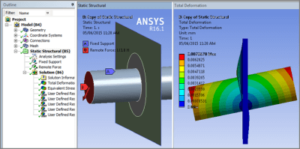
Users can create a contact between the edge of a surface body (shell) and the face of a Flexible body. The surface body Edge is the Contact, and the solid body Face is the Target. If the contact is Bonded and set to MPC, one way to connect node rotations on the surface body is with Constraint Type set to “Target Normal, Couple U to Rot.”
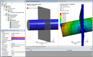
In the example above, the surface body edge tracks the solid body translation and rotation. The surface body edge remains perpendicular to the face on the solid body, as if the surface body is welded to the cylinder.
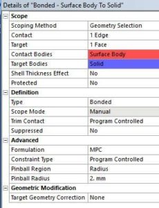
Below, the Constraint Type is set to Program Controlled, which works in more recent Ansys versions, such as v19.2:
In some models involving thin shells that connect to solid bodies, users may wish to simplify the solid body representations by setting them to be Rigid, for example:
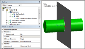
Flexible Solid Bodies with Bonded MPC Contact in Ansys WB
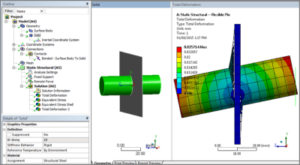
Below, the solid body has been declared to be Rigid. Rotations of the Ansys surface body edge nodes have not been coupled to the rigid body rotation. UX, UY and UZ are bonded to the Ansys rigid body movements, but not rotations:
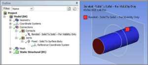
In the platform, a fixed joint can connect the Ansys surface body edge to the rigid body to capture this effect:
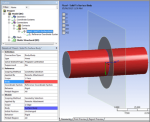
Because the surface body (shell) edge Behavior above is set to Rigid, it translates and rotates with the Ansys rigid body:
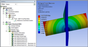
Plots with rigid bodies do not show their movement. The figure above was generated by coating the Ansys rigid body with contact and target elements that do nothing, purely for the sake of plotting:
Conclusions | Connecting Surface Body Edges to Rigid Body Faces
Indeed, Workbench can connect edges of surface bodies (shells) to faces of Flexible solid bodies with Bonded MPC contact. That is, with Contact on the edges, and Target on the faces. In addition, surface body edge nodes respond to translations and rotations of the solid bodies. If, the Contact Type is set to “Target Normal, Couple U to Rot”, or in recent Ansys versions, “Program Controlled”.
If the solid bodies are set Rigid, the edge node rotations are no longer coupled. Complete coupling of translation and rotation is possible with a Fixed Joint set to Rigid on the Ansys surface body edge.
Additional Ansys Software Tips & Tricks Resources
-
- Analyzing normal and Tangential Elastic Foundations in Mechanical
- Why Meshing is Crucial for FEA Fluid Simulations Prior to Prototyping
- For support on Contained Fluid FEA Modeling with HSFLD242 Elements
- For Exporting a Deformed Geometry Shape Post-Analysis in Mechanical
- Moreover, for guidance Multi-Step Analyses in Mechanical
- For Retrieving Beam Reaction Force in a Random Vibration Analysis
- Deploying Ansys Macro Programming vis *USE Command in Mechanical
- For replicating Fatigue Models from Start to Finish in Mechanical
- In addition, setting up Acoustic Simulations of a Silencer
- For a step-by-step guide on 2D to 3D Submodeling in Mechanical
- For modeling Pipe16 Circumferential Stress in Mechanical
- For Support on performing ‘EKILL‘ in Workbench
- APDL Command Objects post-Spectral Analysis
- For Separating DB Database Files from RST Files
- Measuring Geometric Rotation in Mechanical WB
- Explicitly, CAD Geometry Deformation Plasticity
- Offsetting a Temperature Result to Degrees Absolute
- For general guidance on Ansys Post-Processing
- Finally, for basic Ansys Software Installation and License Manager Updates


