Ansys Mechanical (Workbench) makes it easy to review element quality during the development of meshing controls, enabling visually engaging FEA Quality Plots.
Well-shaped elements yield superior results, and help reduce element shape errors during large displacement analysis, such as when using hyperelastic materials with substantial strain.
This article briefly reviews features in the Workbench Mechanical Outline for displaying element quality (1) in color in the Mesh branch, (2) using bar charts of element quality, and (3) plotting element quality in postprocessing after element shapes have been distorted by strain in a model.
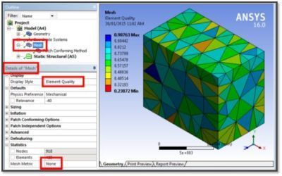
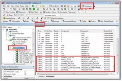
Workbench Mechanical has a new feature for reviewing element quality at the Mesh branch, in order to review the consequences of meshing controls prior to solving a model. First, though, here is a view of mesh metrics as they have been measured in Workbench Mechanical in the last few versions of the software:
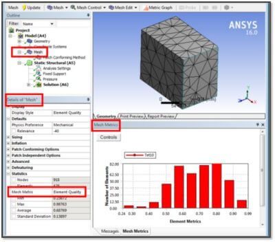
To get the above view of mesh Metrics, click the Mesh branch in the Outline, go to Details of “Mesh”, open the Statistics section of the Details, and use the drop-down list for Mesh Metric to select the metric of interest—in the above figure, “Element Quality” has been chosen. Many choices are available:
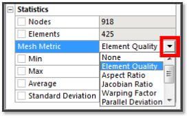
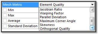
As seen above, the full listing of Mesh Metrics in the Mesh branch in 16.0 is:
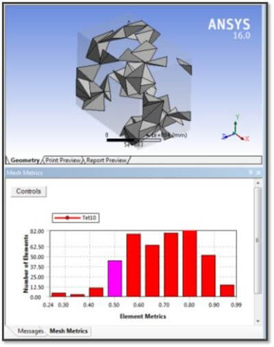
After choosing a quality metric, a bar chart is generated showing how many elements fall into ten Element Metrics zones. If one of the ten bars in the chart is clicked by the user with the cursor, then the elements that fall into the zone of that Element Metric are displayed in the Graphics Window.
In the figure below, the bar with Element Quality around 0.5 has been clicked, and elements with that quality are shown in the Graphics Window, with the geometry shown translucent in order to give context to the element locations:
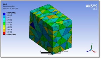
The second means of viewing element quality is to create color plots. What is new in 16.0 is the ability to produce color charts of a variety of element quality metrics. As seen in the figure below, a mesh quality assessment can be shown in a color plot at the Mesh branch.
Note first that in order to get the color plots of element quality, in the Statistics section of Details of “Mesh”, the Mesh Metric must be set to “None”, as seen in the figure above. In the Display Style section of Details of “Mesh” a number of choices are available:
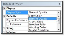
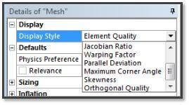
Element coloring is controlled by the “Display Style” drop-down list, as seen in the figure above. Body Color does not show an element quality assessment. The quality plot choices are:
Note that some choices for color plots of element quality are not applicable to tetrahedral elements, such as “Parallel Deviation”, which produces a blank or null result.
The third type of element quality assessment that is available is in postprocessing. The elements in their deformed shape are assessed, at a solution time that can be set by the user. The plots are from the User Defined Results list.
In the figure above, note that several element shape quality assessments can be chosen from the listing of User Defined Results. They include:
Note that some choices, such as Parallel Deviation, are not applicable to tetrahedral elements. Therefore, will produce a null result for element quality plots in Ansys.
As for postprocessing results, the element shapes are assessed in the element deformed condition, with element deformation a consequence of strain in the model. The time of the plot produced will default to “Last”, but can be set by a user to any preferred time value. The FEA Quality Plots figure illustrates this below.
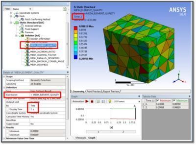
In the figure above, the Element Quality shape assessment has been performed on element shapes as deformed by the solution. In the Tabular Data for this solution result, note the difference in the Minimum and Maximum values at Time values of 1.0 and 2.0. This difference is a result of changing loads on the model between times of 1.0 and 2.0.
Workbench Mechanical offers three ways to view element shape quality assessments.
While preprocessing, color plots of element quality can be performed by choosing Mesh branch details Display Style drop-down list values, while keeping the Mesh Metric choice set to “None”.
At the Mesh branch, a user can go to Details and use the Statistics >Mesh Metric choice to produce bar charts of the range of a number of element shape assessments.
When evaluating Solution results, User Defined Results can be created for several element shape assessments, which are applied to the deformed elements, yielding colored plots.
In the colored plots, values in the Legend can be user-adjusted, and other review tools can be employed, such as Probe, Min and Max, and the usual contour controls.
The latest Ansys Software releases to support with construction geometry
Ansys Mechanical Workbench is a top-tier finite element solver with capabilities to enhance your modeling in the areas of structural, thermal, acoustical, transient, and nonlinear behavior.
Ansys LS-DYNA simulates the response of materials to short duration severe loading. Today, it is the single most used explicit dynamics simulation program worldwide. Best suited for highly technical users.
Ansys EnSight is the market leader for data visualization. Its post-processing tool includes models with more than hundreds of millions of cells, providing engineers with insights unavailable elsewhere.
Ansys Motor-CAD is a specialized electric machine design tool that allows for quick multiphysics simulation over the entire torque-speed working range.
Ansys HFSS simulates 3-Dimensional full-wave electromagnetic fields for accurate and rapid design of high-frequency and high-speed electronic components.
Gain quick, accurate electronic hardware life predictions with Ansys Sherlock, the only PoF (Reliability Physics/Physics of Failure) software that provides insight at each the system, board, and component levels.
A comprehensive solution for designers, engineers, and analysts that spans the full workflow, from design for additive manufacturing (DfAM) to validation, process simulation, and material exploration
Component-level and system-level simulations are provided by the extensive range of photonics simulation to improve performance, lower the price of physical prototyping, and shorten time-to-market.
Ansys Icepak provides specialized electronic cooling solutions that utilize the industry leading CFD solver for T&F flow analyses of integrated circuits, PCBs and electronics.