Ansys Mechanical | How to Model Bolt Threads Using Contacts in Place of Thread Geometry
A useful feature introduced in Ansys Mechanical Workbench is the ability to model bolt threads using contacts instead of modeling the actual thread geometry in Workbench.
Modeling and meshing threaded interfaces is a time consuming and difficult analysis and many times can be unnecessary when the bolt is used simply as a means to transfer loads. In the latest Ansys update, bolt threads can be implemented but also greatly simplified through the use of the Contact Geometry.
Make use of the Bolt Thread Geometry
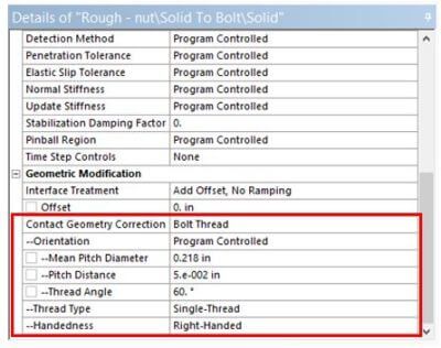
To make use of the Bolt Thread Geometry Correction the user will model straight cylinders for the threaded portion of the bolt interface. Contacts are setup per usual and then under the details section the user defines the thread properties as shown in the figure below.
Things to Note on Modeling Bolt Threads
There are a few things to know about this feature. First, all contact type settings are available except Bonded. Also, in order to obtain more accurate results, it is recommended that the mesh quality in the threaded region is at least 1/4 of the pitch distance.
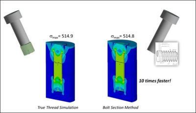
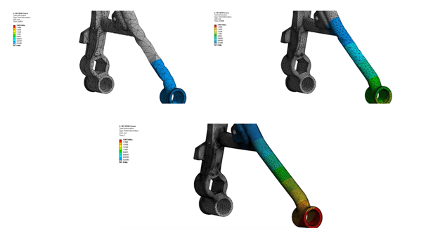
The Bolt Thread Geometry Correction saves significant time by not having to model the threads and create a highly refined mesh. Likewise, solve times are much quicker using this feature and the results are near the accuracy of a true threaded-bolt model. As the figures illustrate above, the max stress from both analyses are almost equal and the stress contour bands look very similar.
Contact for Additional Ansys Mechanical and/or Bolt Thread Support
Finally, we hope that you can make productive use of the Bolt Thread Webinar and supporting resources for your Ansys Mechanical models. For more information, or to request engineering expertise for a particular use-case scenario surrounding bolt thread creation, iterative design simulations, or bolt performance analysis, please contact us here.
Additional Ansys Software Tips & Tricks Resources
-
- Analyzing normal and Tangential Elastic Foundations in Mechanical
- Why Meshing is Crucial for FEA Fluid Simulations Prior to Prototyping
- For support on Contained Fluid FEA Modeling with HSFLD242 Elements
- For Exporting a Deformed Geometry Shape Post-Analysis in Mechanical
- Moreover, for guidance Multi-Step Analyses in Mechanical
- For Retrieving Beam Reaction Force in a Random Vibration Analysis
- Deploying Ansys Macro Programming vis *USE Command in Mechanical
- For replicating Fatigue Models from Start to Finish in Mechanical
- In addition, setting up Acoustic Simulations of a Silencer
- For a step-by-step guide on 2D to 3D Submodeling in Mechanical
- For modeling Pipe16 Circumferential Stress in Mechanical
- For Support on performing ‘EKILL‘ in Workbench
- APDL Command Objects post-Spectral Analysis
- For Separating DB Database Files from RST Files
- Measuring Geometric Rotation in Mechanical WB
- Explicitly, CAD Geometry Deformation Plasticity
- Offsetting a Temperature Result to Degrees Absolute
- For general guidance on Ansys Post-Processing
- Finally, for basic Ansys Software Installation and License Manager Updates


