Display the Vortex Core Region in Ansys (Vortex Structure)
Ansys CFD Post-Processing | Vortex Core Region
In order to help you better understand the processes in your simulation, CFD-Post displays vortex core regions in Ansys software. You will examine the helicity approach for vortex cores in this example, but you should utilize the vortex core method that you believe to be the most useful in your own work.
1. When viewing the Outline tree:
-
- Uncheck the wireframe box under User Locations and Plots.
- Check the box for wall under Cases / elbow1 / fluid.
- Double-click a wall to alter its characteristics.
- Set Transparency to 0.75 and then click Apply on the Render tab.
This allows for both simple visibility of the pipe and visibility of anything inside the pipe.
2. Select Insert/Location/Vortex Core Region from the menu bar
-
- Click OK to accept the suggested name.
3. Set Method to Absolute Helicity and Level to in the Details view
-
- That is, for Vortex Core Region 1 on the Geometry tab.
- Transparency should be set to 0.2 on the Render tab. Tap Apply.
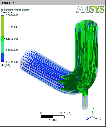
The wall effects, the main pipe’s curve, and the fluid interactions all contribute to the absolute helicity vortex that is seen. Wall effects would have taken over if you had instead chosen the vorticity method.
4. Click on the colored bar in the Color field
-
- Be sure to select the color tab until the bar turns green. Then, tap Apply.
This enhances the contrast between the blue walls and the swirling region.
5. In the 3D Viewer, choose Predefined Camera / Isometric View from the context menu (Y up).
6. Check the box next to Streamline 1 in the Outline tree view.
-
- This demonstrates how the vortex zones influence the streamlines.
7. Remove a check mark from the box next to wall, Streamline 1, and Vortex Core Region 1.
-
- Check the box next to Wireframe.
What is the Vortex Core
The flow zone with uniform vorticity and streamline curvature is known as the vortex core. It must be shear free according to continuum theory. The macroscopic rotation must be accompanied by a concurrent internal rotation of the molecules for it to be thermodynamically self-consistent.
Vortex Region Influence in Fluid Dynamics (CFD)
It is possible for longitudinal vortices to improve heat transfer with little pressure loss. Engineers use computational fluid dynamics (CFD) to study how arrays of longitudinal vortices produced by objects affect local and average heat transfer and fluid flow in a boundary layer that is otherwise laminar.
Additionally, the mechanics of heat transfer augmentation are frequently clarified by conducting heat transfer experiments and hot-wire velocity measurements.
Arrays of co-rotating and counter-rotating longitudinal vortices are often used in experiments, and results will likely demonstrate that each laminar and turbulent effects are important for improving heat transfer.
In the common flow up zone between generators, counter-rotating longitudinal vortices tend to coalesce; in some instances, reduced distances between generators with the common flow down and wide angles of attack were found to improve the heat transfer.
Near-Wall Turbulence Intensity
While arrays of vortices created by objects with greater angles of attack can dramatically modify the flow field and produce a perceptible increase in near-wall turbulence intensity. However, arrays of co-rotating longitudinal vortices frequently display lower vortex merging.
Finally, it is frequently necessary to do an overall performance analysis to decide whether arrays of co-rotating or counter-rotating longitudinal vortices are better suited for enhancing heat transfer.
Additional Ansys Software Tips & Tricks Resources
-
- Analyzing normal and Tangential Elastic Foundations in Mechanical
- Why Meshing is Crucial for FEA Fluid Simulations Prior to Prototyping
- For support on Contained Fluid FEA Modeling with HSFLD242 Elements
- For Exporting a Deformed Geometry Shape Post-Analysis in Mechanical
- Moreover, for guidance Multi-Step Analyses in Mechanical
- For Retrieving Beam Reaction Force in a Random Vibration Analysis
- Deploying Ansys Macro Programming vis *USE Command in Mechanical
- For replicating Fatigue Models from Start to Finish in Mechanical
- In addition, setting up Acoustic Simulations of a Silencer
- For a step-by-step guide on 2D to 3D Submodeling in Mechanical
- For modeling Pipe16 Circumferential Stress in Mechanical
- For Support on performing ‘EKILL‘ in Workbench
- APDL Command Objects post-Spectral Analysis
- For Separating DB Database Files from RST Files
- Measuring Geometric Rotation in Mechanical WB
- Explicitly, CAD Geometry Deformation Plasticity
- Offsetting a Temperature Result to Degrees Absolute
- For general guidance on Ansys Post-Processing
- Finally, for basic Ansys Software Installation and License Manager Updates


