Pinball Region (Radius) with Contact Elements
Fine Tuning the Scope of Joints in Ansys Mechanical WB
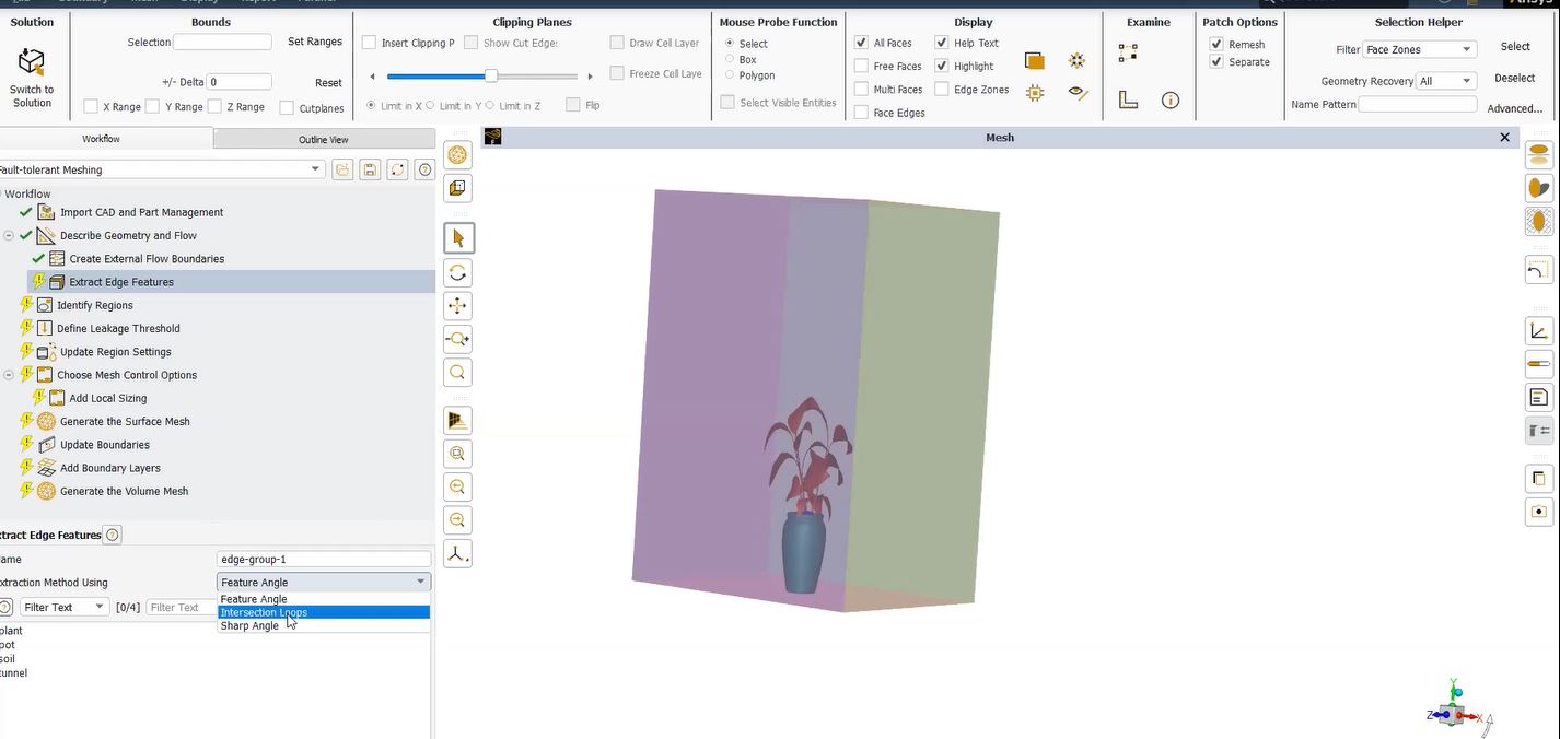
You may not have noticed the advanced “Pinball Region” feature in Ansys Mechanical that allows additional control over the geometric scope of various objects. These objects include Joints, Remote Points, Springs, Point Masses, Remote Force, and Remote Displacement.
The feature is called Pinball Region and is different but analogous to the Pinball Radius used with contact elements.
When one of these objects is created the user must scope it to a surface or set of surfaces. Behind the scenes the solver uses MPC equations to distribute the loads (from the actual joint element or point mass etc.) to a set of element faces on each body.
Using MPC Equations in the Absence of a Pinball Region
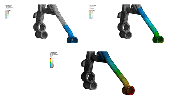
Using the spring example shown in Figure 1 MPC equations would be placed on the entire scope in the absence of this Pinball Region. In this case the entire scope would be too large of an area to distribute the spring load. By defining a reasonable value for the Pinball Region in the details of these objects, the number of element faces is reduced between the spring and the solid element as shown in as shown in Figure 2, (cyan colored elements).
Ansys Pinball Region Feature, A Rapid Alternative
The size of the Pinball Region is shown graphically as a translucent sphere (red or blue typically). Users are still able to create a face imprint in order to define the contact surface where precise control is desired however the Pinball Region feature offers a rapid alternative.
Fine Tune the Scope of Joints in Mechanical | Pinball Region Field
As it is, we are aware that ANSYS does not verify if the contact and target are genuinely in contact outside of the pinball region. It simply assumes they are not in communication and are far away. So, what transpires when the contact and target are situated within the pinball region field? Well, depending on the contact type we have chosen, the answer to that query will vary.
The computer will then verify whether the contact and target are actually touching for frictionless contact (also known as standard contact in MAPDL) and frictional contact. The application will check to see whether they are slipping or maybe separating if they are touching. If they are touching and penetrating, the program will determine if the penetration goes beyond what is permitted and will adapt as necessary.
In other words, for frictionless and frictional contact, the program will perform a variety of checks and changes to ensure the contact behavior is accurately captured if the contact and target parts are close enough to be inside the pinball region.
Additional Ansys Software Tips & Tricks Resources
-
- Analyzing normal and Tangential Elastic Foundations in Mechanical
- Importance of Meshing for Structural FEA and Fluid CFD Simulations
- For support on Contained Fluid FEA Modeling with HSFLD242 Elements
- For Exporting a Deformed Geometry Shape Post-Analysis in Mechanical
- For guidance Multi-Step Analyses in Mechanical
- For Retrieving Beam Reaction Force in a Random Vibration Analysis
- How to display the Vortex Core Region in Ansys Mechanical
- Deploying Ansys Macro Programming vis *USE Command in Mechanical
- For replicating Fatigue Models from Start to Finish in Mechanical
- Setting up Acoustic Simulations of a Silencer
- For a step-by-step guide on 2D to 3D Submodeling in Mechanical
- For modeling Pipe16 Circumferential Stress in Mechanical
- For Support on performing ‘EKILL‘ in Workbench
- APDL Command Objects post-Spectral Analysis
- For Separating DB Database Files from RST Files
- Measuring Geometric Rotation in Mechanical WB
- Explicitly, CAD Geometry Deformation Plasticity
- Offsetting a Temperature Result to Degrees Absolute
- For general guidance on Ansys Post-Processing
- Finally, for basic Ansys Software Installation and License Manager Updates


