Meshing, also known as mesh generation, is the process of generating a two-dimensional and three-dimensional grid; it is dividing complex geometries into elements that can be used to discretize a domain. Ansys Mesh capabilities are often referred to as the gold standard for modeling and simulation of workflows for meshing complex parts.
This process typically consumes a significant portion of the time in acquiring simulation results. As a result, Ansys meshing has created advanced automated mesh generation tools can provide faster and more accurate solutions for CFD (fluid) & FEA Meshing.
Meshing has a significant role when it comes to the engineering simulation process. Creating a high-quality mesh is one of the most critical factors that should be considered to ensure simulation accuracy.
Creating the most appropriate mesh is the foundation of engineering simulations because the mesh influences the accuracy, convergence, and speed of the simulation. Computers cannot solve simulations on the CAD model’s actual geometry shape as the governing equations cannot be applied to an arbitrary shape.
Mesh elements allow governing equations to be solved on predictably shaped and mathematically defined volumes. Typically, the equations solved on these meshes are partial differential equations.
Due to the iterative nature of these calculations, obtaining a solution to these equations is not practical by hand, and so computational methods such as Computational Fluid Dynamics (CFD) and Finite Element Analysis (FEA) are employed.
Creating the most appropriate mesh is the foundation of engineering simulations. Ansys Meshing appropriately adapts to the type of solutions that will be used. Defining the project and setting respective criteria to create the best suited mesh is critical.
For a quick analysis or for the new and infrequent user, a usable mesh can be created in a few short steps. Where possible, Ansys Meshing automatically takes advantage of the available cores in the PC. Utilizing parallel processing via Finite Element Analysis (FEA), and significantly reducing the time to create a mesh.
FEA Meshing of structural models in Ansys Mechanical is all about balancing accuracy versus computational expense. Typically, finer meshes with smaller elements produce more accurate results. However, finer meshes take longer to solve.
However, there is a point where the mesh is refined enough to accurately capture the results. In effect, making additional computational expense unnecessary. This level of refinement is usually problem dependent. In addition, requiring both experience and engineering judgement to determine.
As a general guide, the considerations listed below will help you to create an accurate and efficient mesh in a structural analysis of your own.
Generally, in a Finite Element Analysis (FEA), a finer mesh produces more accurate results. The smaller elements in a finer mesh can more accurately capture stress gradients across the element.
However, adding more elements to a Finite Element Model adds computational expense in two ways:
Of course, managers and engineers alike would like to avoid this unnecessary expense. Consequently, users can restrict areas of high mesh density to areas of interest in their analysis. This is usually confined to areas in the load path of the model, where there is a significant stress level.
Other geometric features, such as fillet radii, may be deployed. This pre-set is often used for large stress concentrations requiring a dense mesh to be able to accurately predict stress. Areas away from the load path or stress concentrations can be meshed with larger elements.
Generally, these areas have insignificant stress levels and can be accurately modelled with large elements.
Ansys Mechanical offers a wide array of tools to help you control your mesh density. There are global mesh controls that control the mesh size. This setting may be established for the entire model as well as local size controls, allowing refinement in areas of interest.
To identify the level of mesh density that provides accurate results, we must first understand convergence. When a result has converged, further mesh refinements in that area will no longer produce a meaningful change in that result. With experience, engineers can determine when they have a sufficiently dense mesh to achieve convergence.
Ansys Mechanical also includes a built-in tool that aids in identifying convergence. Ansys Mechanical will first solve the model with the mesh generated by the user.
Then, the mesh will be refined in locations with high stress. Ansys Mechanical repeats this process until the change in results between each solution reaches a sufficiently low value. Or, based on custom user input, a specified number of solutions is achieved.
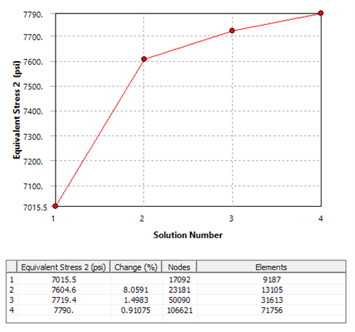
The images below show this tool in action. One image summarizes each solution. In effect, demonstrating the number of nodes and elements in the mesh. This pertains to each solution as well as the change in stress in each solution.
In this example, engineers will observe the change in stress growing smaller and smaller with each mesh refinement, converging on a result.
It is also important to note that a result may not necessarily be able to achieve convergence.
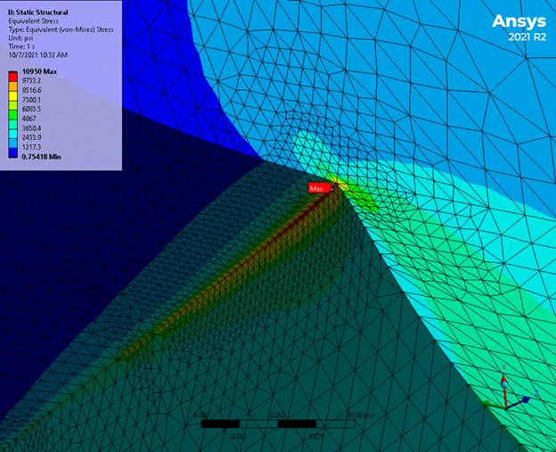
In the case of stress, we refer to this as a stress singularity. These singularities are artificial “hot spots” of stresses that are usually due to modelling assumptions or simplifications. Stress singularities can be caused by geometric features such as sharp corners or edges.
Stress can be thought of as the amount of force transferred through a specific area. In these geometric features, as the element size decreases, the “area” approaches zero, causing the stress to diverge to an infinite value.
Another common source of stress singularities occurs at regions where there is a discontinuity in stiffness in the model. These regions can include things like the boundary where two bodies are in contact or the boundaries of a support.
It is important for a user to be able to identify which areas of stress are artificial stress singularities and which areas are real and need a sufficient mesh to be able to capture the results properly.
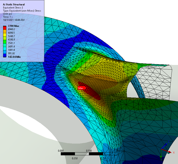
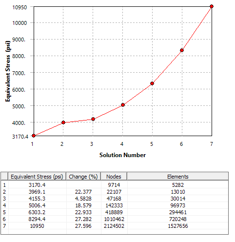
In the example below, the convergence tool was used in a location with a stress singularity. In this case, refining the mesh does not result in smaller change in stress at each solution; it increases the change.
If we continued to refine the mesh in this location, the stress would never converge on a value. Instead, it would diverge, approaching an infinite value.
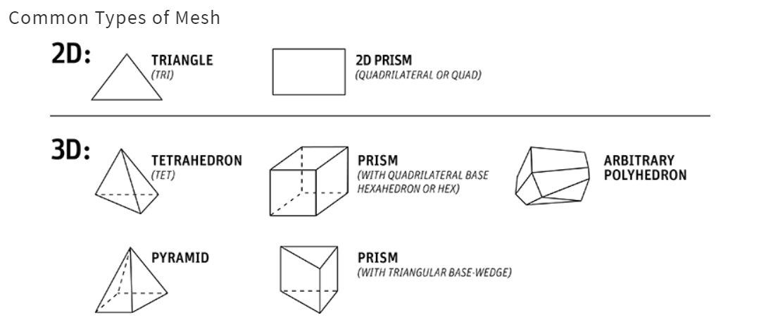
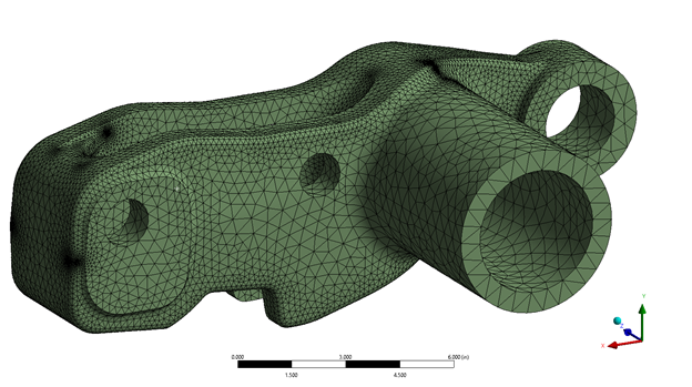
There are two main element shapes used in structural analysis in Ansys Mechanical, hexahedral (hex) or tetrahedral (tet) elements. Other element shapes such as pyramid or wedge-shaped elements also exist, mainly as transitional elements between tet and hex elements.
The ideal element shape for an analysis is usually determined by the geometry that is being represented in the analysis. In general, it is easier to use tet elements than hex elements on highly complex geometry.
To be able to use a hex mesh on complex geometry, the geometry must be divided up into small, more easily meshed sections. This can greatly increase the amount of time spent on an analysis.
However, there is also a trade off in efficiency for tet element. More tet elements need to be used to represent the same geometry than hex elements. It is up to the user to best judge which element shape will be best for an analysis.
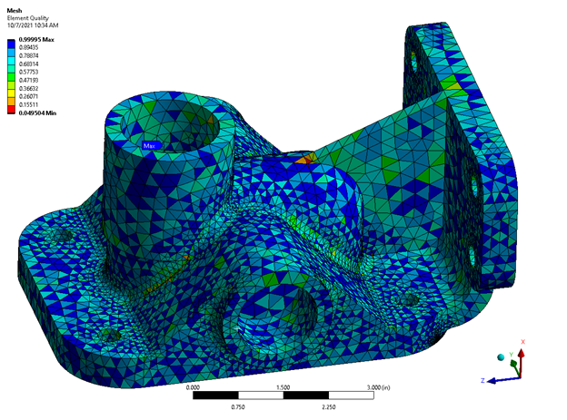
The quality of the shape of elements used in a structural analysis is also an important consideration. Elements with a distorted or skewed shape can produce inaccurate results. Ansys Mechanical includes many different mesh quality criteria that allows the user to check the shape of element.
These quality criteria include element quality, aspect ratio, Jacobian ratio and more . The user can plot each of these mesh quality criteria on their mesh to be able to identify elements of poor quality.
The geometries that design engineers send to analysis engineers are rarely clean enough to import into a fluids modeling program. Fixing these gaps and leaks in the geometry can traditionally take hours, even days.
Therefore, you (as the analysis engineer) should use a CFD software that can wrap a surface mesh around discontinuous geometry.
This automated meshing capability will quickly fill in all the gaps, leaving more time for simulation and results analysis.
When performing a fluid analysis, an inverse fluid volume needs to be created. Generating a fluid volume is achieved by wrapping a box around watertight geometry and combining all the overlapping faces between the solids into one face.
This resolves the intersections between the box and source geometry. The volume can then be extracted and imported into a fluids model.
Employing the “share topology” function creates the requisite flow geometry using Ansys SpaceClaim. With Fluent’s “surface mesh” operation, extracting the flow volume from the void between the boundaries in the geometry is achieved.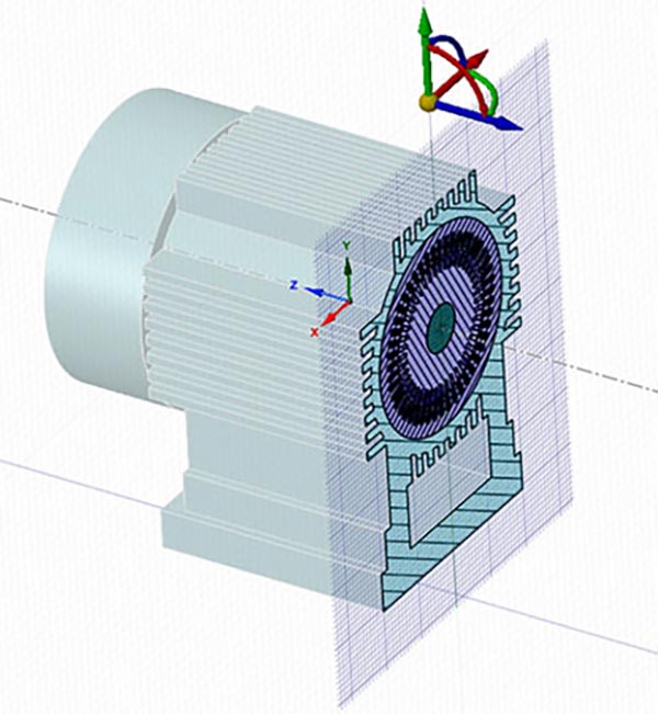
Reducing computational times is achieved by creating fluids models with coarse meshes for large areas and finer meshes for more detailed geometries.
The challenge then becomes linking these disparate meshes into a continuous mesh or sacrificing accuracy by creating non-conformal (mismatching) mesh interfaces.
Conformally linking meshes is a tedious job. It typically requires cleaning up the geometry and manually correcting the meshes so everything fits nicely together.
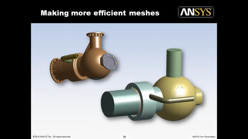
The concept of subdividing a geometry into multiple meshed bodies to leverage strengths of different meshing approaches has existed for a long time. The process of connecting different meshes (whether conformal or not) had varying levels of automation available to the user.
Past approaches, even when automated, were often limited to element type variation on a global level. This resulted in conformal and non-conformal connections between large separately meshed regions.
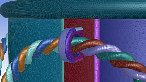
Additionally, recent Ansys updates to Fluent Meshing take the concept of “The right mesh for the right” job to the next level by introducing Mosaic Meshing.
Ansys Fluent’s Mosaic-enabled meshing technology can automatically generate different mesh and element types in different localized or global regions and link these grids conformally.
This approach currently results in a poly-hexcore mesh leveraging the following element types as needed:
It automatically blends between these element types to give you a mesh which is optimized for accuracy and meshing speed. The resulting mesh will have an inflated boundary layer near the walls and a hexahedral core in the fluid free stream.
The two regions (near wall and free stream) will then be blended with a layer of polyhedra. This novel approach means a user is be able to quickly obtain a highly robust, high quality mesh optimized for accurate and stable solutions.
Finally, the more detailed a mesh is, the more accurate the 3D CAD model will be, allowing for high fidelity simulations.
For more information about Ansys Software, FEA Meshing, Stress Singularity, or general inquiries on Fluids Engineering, contact us.
Ansys’ most powerful computational fluid dynamics tool, Fluent, includes well-validated physical modeling capabilities to deliver fast, accurate results across the widest range of CFD and multiphysics applications.
Ansys CFX is a high-performance computational fluid dynamics tool that delivers reliable and accurate solutions quickly for a wide range of applications, including leading capabilities for rotating machinery.
Ansys EnSight is the market leader for data visualization. Its post-processing tool includes models with more than hundreds of millions of cells, providing engineers with insights unavailable elsewhere.
Ansys Polyflow provides advanced fluid dynamics technology for companies in the polymer, glass, metals, and cement processing industries.
Ansys Chemkin-Pro is the gold standard for modeling and simulating complex gas phase and surface chemistry reactions within combustion systems.
Ansys TurboGrid complements rotating machinery simulation with a specialized, easy-to-use tool for the rapid 3D design of rotating machinery components.